background image

— 19 —

— 20 —

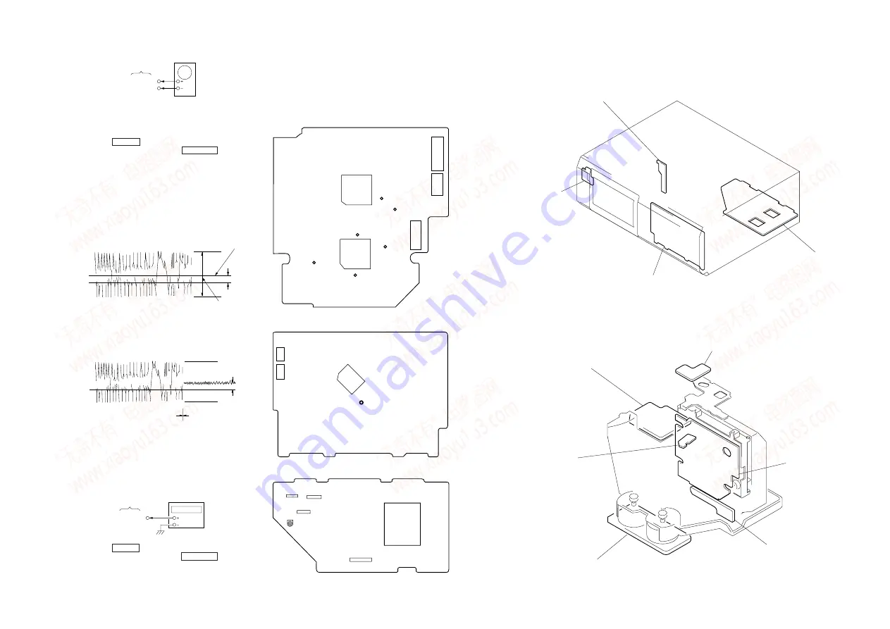
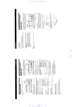
oscilloscope

BD board

TP (TE)
TP (VC)

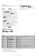
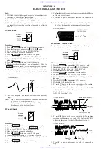
When a general remote commander is not used:
1. Solder lead wires to TP (DVDD) and TP (TOFF) on the BD

board severally.

2. Connect the oscilloscope to TP (TE) of the BD board.
3. Press the  POWER  button and turn ON the power supply.
4. Open the front cover, and press the  PLUS ONE  button.
5. Set the disc (YEDS-18) into the “PLUS ONE” slit.
6. Close the front cover, and chuck the disc.
7. Playback the fifth track of the disc.
8. Short-circuit the lead wire connected at step 1. (The tracking

servo is turned OFF)

9. Check the level B of the oscilliscope's waveform and the A (DC

voltage) of the center of the Traverse waveform.
Confirm the following :
A/B x 100 = less than ± 10%

Traverse waveform

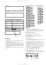
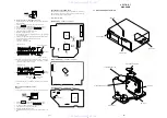
7-1. CIRCUIT BOARDS LOCATION

SECTION  7

DIAGRAMS

POWER SW board

LED board

DISPLAY board

AUDIO board

DISC SENSOR (S) board

TABLE SENSOR board

BD board

SW board

MOTOR board

DISC SENSOR (R) board

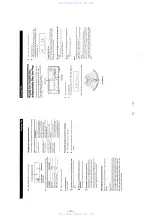
A (DC voltage)

10. Disconnect the lead wire short-circuited at step 8. (The track-

ing servo is turned ON.) Confirm the C (DC voltage) is almost
equal to the A (DC voltage) is step 8.

Traverse waveform

0V

11. Turn OFF the power, and remove the lead wire connected at

step 1.

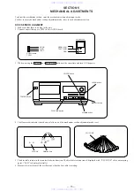
RF PLL Free-run Frequency Check

Procedure :
1. Connect the frequency counter to TP (PLCK) of the BD boar
d.

frequency counter

BD board

B

Center of the waveform

level : 0.7 ± 0.3 Vp-p

C (DC
voltage)

Tracking servo

OFF

Tracking servo

ON

TP (PLCK)

2. Press the  POWER  button and turn ON the power supply.
3. Open the front cover, and press the  PLUS ONE  button.
4. Set the disc (YEDS-18) into the “PLUS ONE” slit.
5. Close the front cover, and chuck the disc.
6. Playback the fifth track of the disc.
7. Confirm that reading on frequency counter is 4.3218 MHz ± 30

kHz.

Adjustment Location :

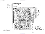
[ BD BOARD ] — CONDUCTOR SIDE —

IC102

IC101

TP

(VC)

TP

(TE)

TP

(FE)

TP

(RF)

TP

(PLCK)

CN101

CN102

CN103

About RV502 on the AUDIO board

RV502 of the AUDIO board requires no adjustments. Please note
that it should be dixed to mechanical center position when you
moved and do not know origin position.

TP

(DVDD)

[ DISPLAY BOARD ] — CONDUCTOR SIDE —

CNP804

IC801

TP301

(ADJ)

CNP801

[ AUDIO BOARD ] — COMPONENT SIDE —

RV502
(No Adjustment)

IC601

CN501

CN801

CN811

T501

0V

www . x ia o y u 1 6 3 . c o m

Q Q 3 7 6 3 1 5 1 5 0

9

9

2

8

9

4

2

9

8

T E L 1 3 9 4 2 2 9 6 5 1 3

9

9

2

8

9

4

2

9

8

0

5

1

5

1

3

6

7

3

Q

Q

TEL  13942296513  QQ  376315150  892498299 

TEL  13942296513  QQ  376315150  892498299 

http://www.xiaoyu163.com

http://www.xiaoyu163.com

Summary of Contents for CDP-CX50

Page 1: ...M CDP CX50 CX571 Photo CDP CX50 US Model Canadian Model AEP Model E Model Australian Model CDP CX50 CX571 UK Model CDP CX571 COMPACT DISC PLAYER www xiaoyu163 com QQ376315150 9 9 2 8 9 4 2 9 8 TEL 13942296513 9 9 2 8 9 4 2 9 8 0 5 1 5 1 3 6 7 3 Q Q TEL 13942296513 QQ 376315150 892498299 TEL 13942296513 QQ 376315150 892498299 http www xiaoyu163 com http www xiaoyu163 com ...
Page 2: ...justments or performance of procedures other than those specified herein may result in hazardous ra diation exposure The laser component in this product is capable of emitting radiation exceeding the limit for Class 1 This appliance is classified as a CLASS 1 LASER product The CLASS 1 LASER PRODUCT MARKING is located on the rear exterior This caution label is located inside the unit 4 987 981 01 4...

Page 3: ...difference generated by the charged electrostatic load etc on clothing and the human body During repair pay attention to electrostatic breakdown and also use the procedure in the printed matter which is included in the repair parts The flexible board is easily damaged and should be handled with care NOTES ON LASER DIODE EMISSION CHECK The laser beam on this model is concentrated so as to be focuse...

Page 4: ...AT button 8 DISC PUSH ENTER button 9 CHECK button º CLEAR button button 0 button p button P button button PLUS ONE button 2 1 8 7 6 5 4 3 0 9 www xiaoyu163 com QQ376315150 9 9 2 8 9 4 2 9 8 TEL 13942296513 9 9 2 8 9 4 2 9 8 0 5 1 5 1 3 6 7 3 Q Q TEL 13942296513 QQ 376315150 892498299 TEL 13942296513 QQ 376315150 892498299 http www xiaoyu163 com http www xiaoyu163 com ...

Page 5: ...uction manual www xiaoyu163 com QQ376315150 9 9 2 8 9 4 2 9 8 TEL 13942296513 9 9 2 8 9 4 2 9 8 0 5 1 5 1 3 6 7 3 Q Q TEL 13942296513 QQ 376315150 892498299 TEL 13942296513 QQ 376315150 892498299 http www xiaoyu163 com http www xiaoyu163 com ...
Page 6: ...63 com QQ376315150 9 9 2 8 9 4 2 9 8 TEL 13942296513 9 9 2 8 9 4 2 9 8 0 5 1 5 1 3 6 7 3 Q Q TEL 13942296513 QQ 376315150 892498299 TEL 13942296513 QQ 376315150 892498299 http www xiaoyu163 com http www xiaoyu163 com ...
Page 7: ...63 com QQ376315150 9 9 2 8 9 4 2 9 8 TEL 13942296513 9 9 2 8 9 4 2 9 8 0 5 1 5 1 3 6 7 3 Q Q TEL 13942296513 QQ 376315150 892498299 TEL 13942296513 QQ 376315150 892498299 http www xiaoyu163 com http www xiaoyu163 com ...

Page 8: ...63 com QQ376315150 9 9 2 8 9 4 2 9 8 TEL 13942296513 9 9 2 8 9 4 2 9 8 0 5 1 5 1 3 6 7 3 Q Q TEL 13942296513 QQ 376315150 892498299 TEL 13942296513 QQ 376315150 892498299 http www xiaoyu163 com http www xiaoyu163 com ...
Page 9: ...tate the illumination assembly in arrow direction D and remove it SECTION 3 DISASSEMBLY 3 Bracket ILLUMINATION 4 Screw BVTT3x6 1 Screw BVTT3x6 claw Expand the front panel in the direction of arrow B to release catching claws B A ILLUMINATION ASSY claw Expand the front panel in the direction of arrow A to release catching claws www xiaoyu163 com QQ376315150 9 9 2 8 9 4 2 9 8 TEL 13942296513 9 9 2 8...

Page 10: ...rewdriver etc 4 Magnet holder 0 Torsion spring Holder 9 BU holder 8 Tension coil spring F 2 6 Two screws PTPWH2 6x8 7 Tension coil spring F 1 5Two screws PTPWH2 6x8 3 Screw BTP2 6x10 www xiaoyu163 com QQ376315150 9 9 2 8 9 4 2 9 8 TEL 13942296513 9 9 2 8 9 4 2 9 8 0 5 1 5 1 3 6 7 3 Q Q TEL 13942296513 QQ 376315150 892498299 TEL 13942296513 QQ 376315150 892498299 http www xiaoyu163 com http www xia...
Page 11: ...P2 6x8 2 SW board 9 Torsion spring Loading 8 Disc holder A Loading lever ASSY Tension coil spring Lever Disc holder B 5 Screw BTP2 6x8 Screw BTP2 6x8 Cover Lever www xiaoyu163 com QQ376315150 9 9 2 8 9 4 2 9 8 TEL 13942296513 9 9 2 8 9 4 2 9 8 0 5 1 5 1 3 6 7 3 Q Q TEL 13942296513 QQ 376315150 892498299 TEL 13942296513 QQ 376315150 892498299 http www xiaoyu163 com http www xiaoyu163 com ...
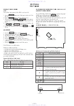
Page 12: ...in this mode Special functions in ADJ mode The buttons function only with the general purpose remote Button Function 3 8 CHECK Tracking servo sled servo OFF Tracking servo sled servo ON S shape observation mode FLUORESCENT INDICATOR TUBE LED ALL LIT AND KEY CHECK MODE Connect TP TP302 AFADJ of the DISPLAY board and the ground with the power OFF and press the POWER button The fluorescent indicator ...

Page 13: ...ng conditions differ according to whether the unit is equipped with the self protection function during errors described later The function serves to maintain the state of the unit when errors occur Special Functions in Aging Mode There are some useful function in the aging mode Disc setting mode 1 Switching of use disuse of protection function in errors 2 Aging cycle count function 3 1 Disc setti...

Page 14: ...icator tube will increase 12 To end aging press the POWER button Error Display Without remote commander for aging mode 1 Turn ON the power of the unit Open the front cover 2 Press the CLEAR 0 and buttons in order 3 When the disc set mode is set the and P LEDs blink The following procedure is the same as in the case With remote commander for aging mode Error code Contents Name Code number No disc i...

Page 15: ...itch PLUS ONE button 0 button button CLEAR button CHECK button 4 The fluorescent indicator tube shows as follows and the mechanism section adjustment mode is set Blinks DISC No Rotation time PLUS ONE 5 The disc table rotates in the counterclockwise direction The disc table rotation time is displayed with PLUS ONE slit as a measuring point LEFt is displayed initially 6 Measure the waveform of the o...

Page 16: ...de 10 If the adjustment is not successful press the CLEAR button to rotate the disc table in the counterclockwise direction and perform steps 6 to 9 Note During the adjustment mode the rotational direction is switched each time the CLEAR button is pressed Immediately after the button is pressed LEFt or rght is displayed to notify of the rotational direction Pressing the CHECK button enters the loa...

Page 17: ...and then turn ON the power Open the door and set a disc in the PLUS ONE slit 2 Turn OFF the power close the door and while pressing the CLEAR and PLUS ONE buttons simultaneously turn ON the power again 3 Press the CHECK button and set the loading mode 4 Press the button and chuck the disc 5 Press or º 0 button to stop the disc holder A slightly away from the disc 6 Rotate and adjust the adjusting ...

Page 18: ...on and turn ON the power supply 2 Open the front cover and press the PLUS ONE button 3 Set the disc YEDS 18 into the PLUS ONE slit 4 Close the front cover and chuck the disc 5 Press the POWER button and turn OFF the power 6 Connect the oscilloscope to TP RF of the BD board 7 Connect TP ADJ of the DISPLAY board and the ground with a lead wire 8 Press the POWER button and turn ON the power 9 Playbac...

Page 19: ... the power and remove the lead wire connected at step 1 RF PLL Free run Frequency Check Procedure 1 Connect the frequency counter to TP PLCK of the BD board frequency counter BD board B Center of the waveform level 0 7 0 3 Vp p C DC voltage Tracking servo OFF Tracking servo ON TP PLCK 2 Press the POWER button and turn ON the power supply 3 Open the front cover and press the PLUS ONE button 4 Set t...

Page 20: ...Q Q 3 7 6 3 1 5 1 5 0 9 9 2 8 9 4 2 9 8 T E L 1 3 9 4 2 2 9 6 5 1 3 9 9 2 8 9 4 2 9 8 0 5 1 5 1 3 6 7 3 Q Q TEL 13942296513 QQ 376315150 892498299 TEL 13942296513 QQ 376315150 892498299 http www xiaoyu163 com http www xiaoyu163 com ...
Page 21: ...Q Q 3 7 6 3 1 5 1 5 0 9 9 2 8 9 4 2 9 8 T E L 1 3 9 4 2 2 9 6 5 1 3 9 9 2 8 9 4 2 9 8 0 5 1 5 1 3 6 7 3 Q Q TEL 13942296513 QQ 376315150 892498299 TEL 13942296513 QQ 376315150 892498299 http www xiaoyu163 com http www xiaoyu163 com ...
Page 22: ...Q Q 3 7 6 3 1 5 1 5 0 9 9 2 8 9 4 2 9 8 T E L 1 3 9 4 2 2 9 6 5 1 3 9 9 2 8 9 4 2 9 8 0 5 1 5 1 3 6 7 3 Q Q TEL 13942296513 QQ 376315150 892498299 TEL 13942296513 QQ 376315150 892498299 http www xiaoyu163 com http www xiaoyu163 com ...
Page 23: ...Q Q 3 7 6 3 1 5 1 5 0 9 9 2 8 9 4 2 9 8 T E L 1 3 9 4 2 2 9 6 5 1 3 9 9 2 8 9 4 2 9 8 0 5 1 5 1 3 6 7 3 Q Q TEL 13942296513 QQ 376315150 892498299 TEL 13942296513 QQ 376315150 892498299 http www xiaoyu163 com http www xiaoyu163 com ...
Page 24: ...Q Q 3 7 6 3 1 5 1 5 0 9 9 2 8 9 4 2 9 8 T E L 1 3 9 4 2 2 9 6 5 1 3 9 9 2 8 9 4 2 9 8 0 5 1 5 1 3 6 7 3 Q Q TEL 13942296513 QQ 376315150 892498299 TEL 13942296513 QQ 376315150 892498299 http www xiaoyu163 com http www xiaoyu163 com ...
Page 25: ...Q Q 3 7 6 3 1 5 1 5 0 9 9 2 8 9 4 2 9 8 T E L 1 3 9 4 2 2 9 6 5 1 3 9 9 2 8 9 4 2 9 8 0 5 1 5 1 3 6 7 3 Q Q TEL 13942296513 QQ 376315150 892498299 TEL 13942296513 QQ 376315150 892498299 http www xiaoyu163 com http www xiaoyu163 com ...
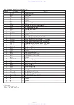
Page 26: ...reates a focusing phase compensation constant between FD and FA pins Creates a focusing phase compensation constant between FA and FE pins FE signal output Connects the FE signal gain setting resistor between TE pins Analog signal Ground Single end output of CV and CV pin signal Spindle amplifier input Gain setting resistor is connected when the spindle 12cm mode Works together with the SPD pin to...

Page 27: ...tput for external VCO control PLL Ground for the built in VCO Be sure to connect to 0 when not in use Connected to a current adjusting resistor for the PDO output Built in VCO power supply Adjusts the VCO frequency range Digital Ground Be sure to connect to 0 Slice level control EFM signal output Slice level control EFM signal input Test input Incorporates a pull down resistor Be sure to connect t...

Page 28: ...W output Subcode frame sync signal output Rises when the subcode is in a standby Subcode read clock input Schmidt input Connect to 0V when not in use 7 35 kHz sync signal output divided from the crystal oscillation Subcode Q output standby output Read write control input Schmidt input Subcode Q output Command input from the microprocessor Command input fetching clock input or subcode extracting cl...

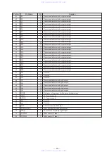
Page 29: ... output Sled motor Internal circuit direction output Loading motor Out a direction output PWM output Loading motor In a direction output PWM output Table rotation Left a direction output PWM output Table rotation Right a direction output PWM output Loading out SW input Loading in SW input Not used Disc sensor analog input Operation key 0 analog input Operation key 1 analog input Not used Test mode...

Page 30: ...dicator tube segment output Fluorescent indicator tube segment output Fluorescent indicator tube segment output Fluorescent indicator tube segment output Fluorescent indicator tube segment output Fluorescent indicator tube segment output Fluorescent indicator tube segment output Fluorescent indicator tube segment output Fluorescent indicator tube segment output Fluorescent indicator tube segment o...

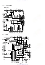
Page 31: ...RQ FSX SBCK SFSY PW EMPH CF2 DOUT TGL TOFF TEST3 JP JP PCK FSEQ VDD CONT1 CONT2 CONT3 CONT4 CONT5 C1 C2 ERROR DETECTION CORRECTION FLAG PROTCESS IC102 LC78622E 1 2 3 4 5 6 7 8 9 10 11 12 13 14 15 16 64 VCC1 LDS LDD BHI PHI LF2 VR REFI VCC2 FSS DRF CE DAT CL CLK DEF FD FA FA FE FE SL SL AGND SP SPI SPG SP SPD SLEQ SLD JP NC TBC FSC DGND SLI SLC RFS RFSM CV CV SLOF HFL TES TOFF TGL JP FIN2 FINI E F ...

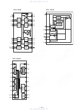
Page 32: ...EL SHIFT LEVEL SHIFT REGULATOR RESET Vcc IC103 LA6541 IC601 BA6780 VIN2 FIN2 RIN2 CT2 VEE FBIN FBIN OUT2 OUT2 VIN1 FIN1 REVERSIBLE DRIVER FWD REV CONTROLLER COVERNER DRIVER FWD REV CONTROLLER COVERNER LOAD CURRENT DETECTION AMPLIFIER COVERNER OUTPUT REFERENCE VOLTAGE OUTPUT LOW VOLTAGE OUTPUT RIN1 IOUT VEE VEE VCC VREF VREG VCC OUT1 OUT1 18 17 16 15 1 2 3 4 5 6 7 8 9 14 13 12 11 10 www xiaoyu163 c...

Page 33: ...RD POWER E 9 1 575 651 21 CORD POWER CX50 AEP G SP CX571 AEP G SP AUS 9 1 590 926 11 CORD POWER US CND 9 1 696 845 11 CORD POWER CX50 AUS 9 1 769 639 11 CORD POWER CX571 UK 10 1 569 007 11 ADAPTOR CONVERSION 2P CX50 E 11 1 665 903 11 LED BOARD 12 X 4948 515 1 ILLUMINATION ASSY 1 4 987 999 11 CASE 2 3 704 366 01 SCREW CASE M3X8 3 4 987 981 01 PANEL BACK CX50 US 3 4 987 981 11 PANEL BACK CX50 CND 3 ...

Page 34: ...8 084 1 LID ASSY 52 4 987 941 01 KNOB JOG 53 4 988 674 01 CUSHION CLOSE 54 3 008 600 01 EMBLEM 5 AR SONY 55 4 987 877 01 PANEL FRONT CX50 55 4 987 877 21 PANEL FRONT CX571 56 4 987 955 01 WINDOW FL 57 X 4948 480 1 BUTTON MAIN ASSY 58 3 354 963 01 DAMPER 59 A 4699 531 A DISPLAY BOARD COMPLETE 60 4 977 589 01 BUTTON POWER 63 not supplied 63 61 60 55 54 66 68 62 63 FL801 66 58 69 69 52 56 67 57 65 64...

Page 35: ...439 01 HOLDER TABLE 107 1 782 221 11 WIRE FLAT TYPE 10 CORE 108 4 991 167 01 COVER TRANSFORMER 109 3 704 198 51 SUPPORT PC 110 A 4699 533 A AUDIO BOARD COMPLETE US CND 109 not supplied Les composants identifiés par une marque sont critiques pour la sécurité Ne les remplacer que par une piéce portant le numéro spécifié The components identified by mark or dotted line with mark are critical for safe...

Page 36: ...NSION COIL 227 4 988 441 01 SPRING F 2 TENSION COIL 228 4 957 577 21 SCREW PTP WH 2 6X8 DIA 10 201 1 663 975 11 SW BOARD 202 4 988 427 01 COVER CAM 203 4 988 420 01 SLIDER LOADING 204 4 988 436 01 SPRING LOADING TORSION 205 4 988 418 01 HOLDER A DISC 206 4 988 417 01 SLIDER CAM 207 4 988 433 01 SLIDER LOCK 208 X 4948 020 1 LEVER ASSY LOADING 209 4 988 438 01 SPRING LEVER TENSION COIL 210 4 988 437...

Page 37: ... 1 MOTOR ASSY TABLE 251 1 663 971 11 TABLE SENSOR BOARD 252 4 988 414 01 BELT 253 4 988 423 01 GEAR A LOADING 254 4 988 425 01 PULLEY 255 4 988 424 01 GEAR TABLE 256 4 988 432 01 GEAR B LOADING 258 6 252 5 251 254 254 253 256 9 7 7 260 257 M61 259 M62 255 www xiaoyu163 com QQ376315150 9 9 2 8 9 4 2 9 8 TEL 13942296513 9 9 2 8 9 4 2 9 8 0 5 1 5 1 3 6 7 3 Q Q TEL 13942296513 QQ 376315150 892498299 T...

Page 38: ...OOF M101 X 2646 110 1 T T CHASSIS ASSY MG F SPINDLE M102 X 2625 769 1 MOTOR GEAR ASSY MB RP SLED Les composants identifiés par une marque sont critiques pour la sécurité Ne les remplacer que par une piéce portant le numéro spécifié The components identified by mark or dotted line with mark are critical for safety Replace only with part number specified www xiaoyu163 com QQ376315150 9 9 2 8 9 4 2 9...

Page 39: ...OR Q301 8 729 141 26 TRANSISTOR 2SC3622A LK Q302 8 729 029 56 TRANSISTOR DTA144ESA Q303 8 729 030 03 TRANSISTOR DTC144ESA TP Q313 8 729 141 26 TRANSISTOR 2SC3622A LK Q401 8 729 141 26 TRANSISTOR 2SC3622A LK Q402 8 729 029 56 TRANSISTOR DTA144ESA Q403 8 729 030 03 TRANSISTOR DTC144ESA TP Q413 8 729 141 26 TRANSISTOR 2SC3622A LK Q501 8 729 029 56 TRANSISTOR DTA144ESA Q701 8 729 140 97 TRANSISTOR 2SB...

Page 40: ...C CHIP 0 0033uF 10 50V C110 1 163 809 11 CERAMIC CHIP 0 047uF 10 25V C111 1 164 492 11 CERAMIC CHIP 0 15uF 10 16V C112 1 163 009 11 CERAMIC CHIP 0 001uF 10 50V C113 1 164 492 11 CERAMIC CHIP 0 15uF 10 16V C114 1 164 492 11 CERAMIC CHIP 0 15uF 10 16V C115 1 164 232 11 CERAMIC CHIP 0 01uF 50V C116 1 164 232 11 CERAMIC CHIP 0 01uF 50V C117 1 163 001 11 CERAMIC CHIP 220PF 10 50V C118 1 107 823 11 CERA...

Page 41: ...216 099 00 METAL CHIP 120K 5 1 10W R124 1 216 093 00 METAL CHIP 68K 5 1 10W R125 1 216 089 91 METAL GLAZE 47K 5 1 10W R126 1 216 037 00 METAL CHIP 330 5 1 10W R127 1 216 089 91 METAL GLAZE 47K 5 1 10W R128 1 216 077 00 METAL CHIP 15K 5 1 10W R129 1 216 069 00 METAL CHIP 6 8K 5 1 10W R130 1 216 113 00 METAL CHIP 470K 5 1 10W R131 1 216 113 00 METAL CHIP 470K 5 1 10W R132 1 216 065 00 METAL CHIP 4 7...

Page 42: ...K 5 1 4W R823 1 249 429 11 CARBON 10K 5 1 4W R824 1 249 429 11 CARBON 10K 5 1 4W R826 1 249 429 11 CARBON 10K 5 1 4W R827 1 249 429 11 CARBON 10K 5 1 4W R828 1 249 437 11 CARBON 47K 5 1 4W R829 1 249 429 11 CARBON 10K 5 1 4W R830 1 247 807 31 CARBON 100 5 1 4W R831 1 249 407 11 CARBON 150 5 1 4W F R832 1 249 410 11 CARBON 270 5 1 4W F R833 1 247 807 31 CARBON 100 5 1 4W R834 1 249 429 11 CARBON 10...

Page 43: ...2 367 12 MAGNET 224 1 777 874 11 WIRE FLAT TYPE 16 CORE 301 8 848 379 31 OPTICAL PICK UP KSS 213B S N FL801 1 517 517 11 INDICATOR TUBE FLUORESCENT M61 X 4948 434 1 MOTOR ASSY LOADING M62 X 4948 434 1 MOTOR ASSY TABLE M101 X 2646 110 1 MOTOR ASSY SPINDLE M102 X 2625 769 1 MOTOR ASSY SLED T501 1 429 670 21 TRANSFORMER POWER US CND T501 1 429 671 21 TRANSFORMER POWER CX50 AEP G SP AUS CX571 AEP G UK...

Page 44: ...646 79 SCREW BVTP 3X8 TYPE2 N S 7 7 621 770 67 SCREW PWH 2 6X6 8 7 685 872 09 SCREW BVTT 3X8 S 9 7 685 132 19 SCREW BTP 2 6X5 TYPE2 N S 10 7 621 772 20 SCREW B 2X5 11 7 682 255 15 SCREW P 2X3 12 7 685 135 19 SCREW P 2 6X10 www xiaoyu163 com QQ376315150 9 9 2 8 9 4 2 9 8 TEL 13942296513 9 9 2 8 9 4 2 9 8 0 5 1 5 1 3 6 7 3 Q Q TEL 13942296513 QQ 376315150 892498299 TEL 13942296513 QQ 376315150 89249...

Page 45: ...Japan 1997 3 Published by Service and Safety Engineering Dept Shibaura www xiaoyu163 com QQ376315150 9 9 2 8 9 4 2 9 8 TEL 13942296513 9 9 2 8 9 4 2 9 8 0 5 1 5 1 3 6 7 3 Q Q TEL 13942296513 QQ 376315150 892498299 TEL 13942296513 QQ 376315150 892498299 http www xiaoyu163 com http www xiaoyu163 com ...
Reviews: