ǪÇÃëº
ǪÇÃëº
19
OTHERS
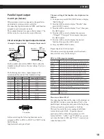
Parallel input/output
D-sub 9 pin (female)
When a simple circuit is connected to the parallel in/
out terminals, remote control is available.
By connecting input terminal and GND, each function
assigned to each terminal can work.
These output terminals are open collector output. The
LEDs can be lit on to show the status of the unit.
Circuit examples for input/output terminals
<Example of output circuit>
By the parallel select of the MENU Mode, either the
standard setting (Preset) or the user setting (User) can
be selected.
The following chart shows inputs/outputs of the
terminals and functions of the standard settings.
Pin number Input/output Function
Names in MENU Mode
1
Input
PLAY
PIN1
2
Input
PAUSE
PIN2
3
Input
STOP
PIN3
4
Input
AMS+
PIN4
5
Input
AMS–
PIN5
6
GND
---
7
Output
PLAY
POUT1
8
Output
PAUSE
POUT2
9
Output
NO DISC
POUT3
Pin number
In the user setting, the following functions can be
assigned to PIN1 to PIN5, to POUT1 to POUT3 in the
MENU Mode.
Input/output of each pin is fixed.
The user setting of the function of each pin is set as
follows.
1 In stop mode, press MENU/EXIT button to display
“MENU Mode”.
2 Turn the AMS control to display “Parallel”, then
press the AMS control.
3 Turn the AMS control to display “User”, then press
the AMS control.
4 Turn the AMS control to display the pin name
(“P.Input1” “P.Output1” for example), then press
the AMS control.
5 Turn the AMS control to display the desired
function, then press the AMS control.
6 Press the MENU/EXIT button.
Repeat steps 4 and 5 for each pin.
When the user setting of parallel select has already
been selected, carry out from step 4.
PIN1 to PIN5 (input terminals)
PLAY/PAUSE
The same function as PLAY/PAUSE in the main unit
PLAY
The same function as PLAY in the remote control
PAUSE
The same function as PAUSE in the remote control
STOP
The same function as STOP in the main unit
AMS+
The same function as AMS+ in the remote control
AMS–
The same function as AMS- in the remote control
FF
The same function as FF in the main unit
REW
The same function as REW in the main unit
MARK
The same function as MARK in the remote control
LOCATE
The same function as LOCATE in the remote control
EJECT
The same function as EJECT in the main unit
Fader PLAY
Carry out the fader play
1 Track PLAY– The same function as Number buttons (1–20) in the
20 Track PLAY remote control
OFF
No operation
How to use Fader PLAY
By connecting the fader of the mixer to the terminal on
the CDP-D11 which is set as the Fader PLAY of the
parallel input, starting play and pause at the beginning
of the next track are synchronized to the fader.
This can be used in the mixer equipped with fader
remote function in which –
∞
position (lowest
position) is OFF and the other positions are ON.
In the CDP-D11, “AMS+” and “PAUSE” are carried
out when the fader is OFF, and “PLAY” is carried out
when the fader is ON.
<Example of input circuit>
CDP-D11
Output
terminals
(7th to 9th)
GND
(6th)
Input
terminals
(1st to 5th)
GND
(6th)
CDP-D11
Summary of Contents for CDP-D11
Page 24: ...OTHERS 24 Printed in Japan ...


