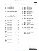
5-1. IC PIN FUNCTION
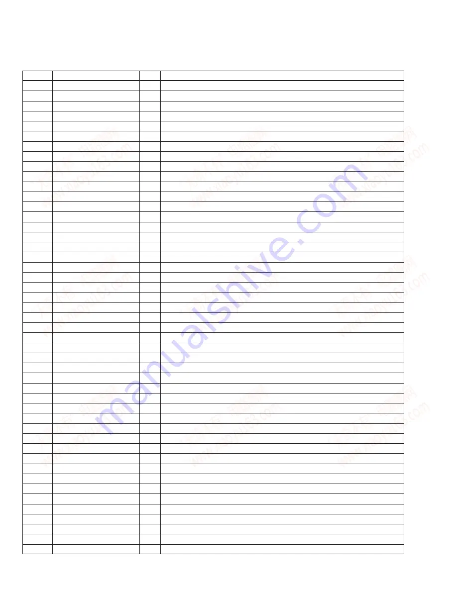
• IC601
µ
PD78044AGF (SYSTEM CONTROL, FL DRIVER)
Pin No.
Pin Name
I/O
Function
1-7
T6-T0
O
FL display grid output
8
VDD
—
+5V power supply
9
CLK
O
Serial clock output to DSP (CXD2507AQ).
10
DATA
O
Serial data output to DSP (CXD2507AQ).
11
—
—
Fixed at Ground.
12
XLAT
O
Serial data latch pulse output to DSP (CXD2507AQ).
13
PRGL
O
Serial data latch pulse output to D/F DAC (PCM1710U).
14
SQCLK
O
Sub code Q data read clock output to DSP (CXD2507AQ).
15
—
—
Not used. (Open)
16
SUBQ
I
Sub code Q data input from DSP (CXD2507AQ).
17
RESET
I
System reset input (“ L ”= Active)
18
INSW
I
S292 (load in switch) input
19
OUTSW
I
S291 (load out switch) input
20
AVSS
—
Ground
21
LDOUT
O
Output for rotating M903 (loading motor) in the loading out direction.
22
LDIN
O
Output for rotating M903 (loading motor) in the loading in direction.
23
ADJ
I
Test mode input. (“ L ”= Stops GFS check)
24
AFADJ
I
Test mode input. Fixed at “H”. (“ L ”= Test mode)
25
MODE
I
Not used. (Fixed at “ H ”.)
26-28
KEY2-KEY0
I
Key AD input
29
AVDD
—
+5V power supply
30
AVREF
—
+5V power supply
31
—
—
Fixed at Ground.
32
—
—
Not used. (Open)
33
VSS
—
Ground
34
X1
I
Clock input (5MHz)
35
X2
O
Clock output (5MHz)
36
BDRST
O
BD reset output
37
BDPOWER
O
BD power ON/OFF output
—
Not used. (Open)
I
SENS input from DSP (CXD2507AQ).
O
Not used. (Open)
O
Focus switch output
O
Audio bus output
—
Not used. (Open)
I
Sub code sync S0+S1 detection input
I
JOG input
—
Not used. (Open)
I
Audio bus input
48
IC (VPP)
—
Connected to Ground.
49
JOG0
I
JOG input
50, 51
—
—
Not used. (Open)
52
VDD
—
+5V power supply
53-70
S22-S5
O
FL display segment output
71
VLOAD
—
-28V power supply for driving FL display.
72-76
S4-S0
O
FL display segment output
77-80
T10-T7
O
FL display grid output
SECTION 5
DIAGRAMS
www. xiaoyu163. com
QQ 376315150
9
9
2
8
9
4
2
9
8
TEL 13942296513
9
9
2
8
9
4
2
9
8
0
5
1
5
1
3
6
7
3
Q
Q
TEL 13942296513 QQ 376315150 892498299
TEL 13942296513 QQ 376315150 892498299


