– 73 –
#2
#2
#2
#1
#1
#1
#1
#1
#2
#2
#4
#2
#2
#2
#5
#5
#5
#1
F901
20
1
2
3
4
5
6
7
8
9
10
17
11
12
13
14
15
15
16
18
TU10
21
19
MG-363S-121
22
23
24
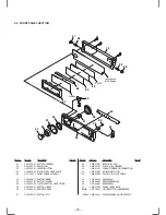
SECTION 5
EXPLODED VIEWS
NOTE:
• The mechanical parts with no reference
number in the exploded views are not supplied.
• Items marked “*” are not stocked since
they are seldom required for routine service.
Some delay should be anticipated
when ordering these items.
• -XX and -X mean standardized parts, so
they may have some difference from the
original one.
• Color Indication of Appearance Parts
Example :
KNOB, BALANCE (WHITE) ... (RED)
Parts Color Cabinet’s Color
• Accessories and packing materials and
hardware (# mark) list are given in
the last of this parts list.
The components identified by
mark
!
or dotted line with mark.
!
are critical for safety.
Replace only with part number
specified.
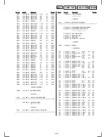
Ref. No.
Part No.
Description
Remark
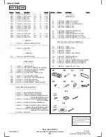
5-1. CHASSIS SECTION
N
N
Ref. No.
Part No.
Description
Remark
• Abbreviation
G : German model
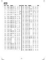
1
3-022-316-11 COVER
2
X-3375-070-1 PANEL ASSY, SUB
3
3-022-338-01 BUTTON (EJECT)
*
4
1-668-088-21 RELAY BOARD
5
X-3375-068-1 LOCK ASSY
6
X-3375-066-1 BRACKET (GEAR) ASSY
7
3-953-235-01 DAMPER, OIL
8
3-011-170-01 GEAR (HOLDER)
9
3-341-752-11 WASHER, POLYETHYLENE
*
10
A-3294-672-A MAIN BOARD, COMPLETE (AEP,UK)
*
10
A-3294-675-A MAIN BOARD, COMPLETE (G)
*
11
3-014-819-01 HEAT SINK (REG2)
*
12
3-022-317-11 BRACKET (AMP)
*
13
3-022-336-01 HEAT SINK
*
14
3-031-812-01 PLATE (TUX-B), SHIELD
15
3-915-923-01 SCREW, GROUND POINT
16
3-022-335-01 BRACKET (MD)
17
3-022-311-01 CHASSIS
18
1-475-684-11 INVERTER UNIT, EL
19
1-776-527-71 CORD (WITH CONNECTOR) (ISO) (POWER)
20
1-777-246-21 CORD (WITH CONNECTOR) (ANTENNA)
21
3-023-539-02 SHEET (INSULATING)
22
3-831-441-99 CUSHION (SP)
*
23
4-871-306-02 RUBBER (A)
*
24
3-016-299-01 CUSHION
F901
1-532-877-11 FUSE (BLADE TYPE) (AUTO FUSE) 10A
TU10
A-3282-045-A TUNER UNIT (TUX-012(E))
Summary of Contents for CDX-C7850R
Page 3: ... 3 SECTION 1 GENERAL This section is extracted from instruction manual ...
Page 4: ... 4 ...
Page 5: ... 5 ...
Page 6: ... 6 ...
Page 7: ... 7 ...
Page 8: ... 8 ...
Page 9: ... 9 ...
Page 10: ... 10 ...
Page 11: ... 11 ...
Page 12: ... 12 ...
Page 39: ... 47 48 CDX C7850R Page 51 ...
Page 41: ...CDX C7850R 51 52 Page 65 Page 66 Page 47 ...
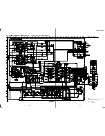
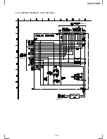
Page 49: ... 67 4 18 SCHEMATIC DIAGRAM RELAY SECTION Page 63 Page 60 Page 60 CDX C7850R ...

