


CDX-GT572
3
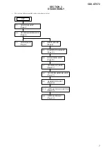
1.
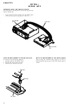
SERVICE NOTE
..................................................... 4
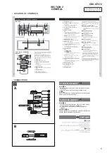
2. GENERAL
Location of Controls ....................................................... 5
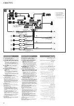
Connections
....................................................................
5
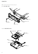
3. DISASSEMBLY
3-1. Sub Panel Assy ............................................................... 8
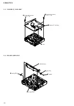
3-2. CD Mechanism Block ..................................................... 8
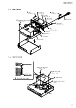
3-3. Main Board ..................................................................... 9
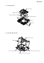
3-4. Servo
Board
.................................................................... 9
3-5. Chassis (T) Sub Assy ...................................................... 10
3-6. Roller
Arm
Assy
.............................................................. 10
3-7. Chassis
(OP)
Assy
........................................................... 11
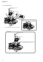
3-8. Chucking Arm Sub Assy ................................................. 11
3-9. Sled
Motor
Assy
.............................................................. 12
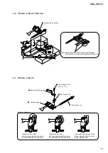
3-10. Optical Pick-up Section .................................................. 13
3-11. Optical Pick-up ............................................................... 13
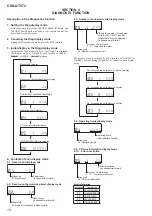
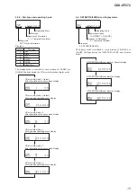
4.
DIAGNOSIS FUNCTION
..................................... 14
TABLE OF CONTENTS
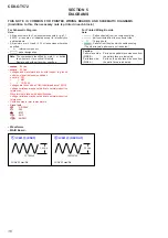
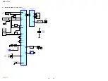
5. DIAGRAMS
5-1. Block Diagram –Main Section– ..................................... 17
5-2. Block Diagram –Display Section– ................................. 18
5-3. Printed Wiring Board –Main Section– ............................ 19
5-4. Schematic Diagram –Main Section (1/3)– ...................... 20
5-5. Schematic Diagram –Main Section (2/3)– ...................... 21
5-6. Schematic Diagram –Main Section (3/3)– ...................... 22
5-7. Printed Wiring Boards –Sub Section– ............................ 23
5-8. Schematic Diagram –Sub Section– ................................. 23
5-9. Printed Wiring Boards –Key Section– ............................ 24
5-10. Schematic Diagram –Key Section– ................................ 25
6.
EXPLODED VIEWS
6-1. Main
Section
................................................................... 29
6-2. Front Panel Section ......................................................... 30
6-3. CD Mechanism Section (MG-101TC-188//Q) ............... 31
7.
ELECTRICAL PARTS LIST
.............................. 32


