
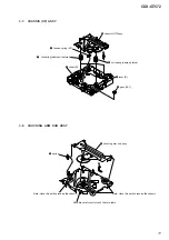
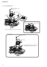
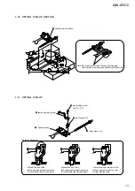


CDX-GT572
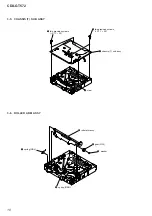
6
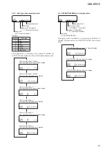
L
R
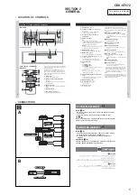
FRONT
AUDIO OUT
REAR
AUDIO OUT
BUS
CONTROL IN
REMOTE
IN
REAR
AUDIO OUT
FRONT
BUS
IN
SUB OUT (MONO)
2
4
5
1
3
BUS AUDIO IN
from car antenna (aerial)
desde la antena del automóvil
AMP REM
Max. supply current 0.3 A
Corriente máx. de alimentación de 0,3 A
Fuse (10 A)
Fusible (10 A)
Blue/white striped
Con rayas azules y blancas
Red
Rojo
Yellow
Amarillo
White
Blanco
Green
Verde
Purple
Morado
White/black striped
Con rayas blancas y negras
Grey/black striped
Con rayas grises y negras
Green/black striped
Con rayas verdes y negras
Grey
Gris
Left
Izquierdo
Right
Derecho
Left
Izquierdo
Right
Derecho
ANT REM
Black
Negro
Blue
Azul
Max. supply current 0.1 A
Corriente máx. de alimentación de 0,1 A
Purple/black striped
Con rayas moradas y negras
*
1
*
2
*
1
*
1
RCA pin cord (not supplied)
*
2
Insert with the cord upwards.
*
1
Cable con terminales RCA
(no suministrado)
*
2
Insertar con el cable hacia arriba.
2
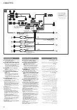
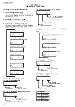
Connection diagram
1
To a metal surface of the car
First connect the black ground (earth) lead, then connect the
yellow and red power supply leads.
2
To the power antenna (aerial) control lead or
power supply lead of antenna (aerial) booster
Notes
•
It is not necessary to connect this lead if there is no power
antenna (aerial) or antenna (aerial) booster, or with a
manually-operated telescopic antenna (aerial).
•
When your car has a built-in FM/MW/SW antenna (aerial)
in the rear/side glass, see “Notes on the control and power
supply leads.”
3
To AMP REMOTE IN of an optional power
amplifi er
This connection is only for amplifi ers. Connecting any other
system may damage the unit.
4
To the +12 V power terminal which is
energized in the accessory position of the
ignition switch
Notes
•
If there is no accessory position, connect to the +12 V
power (battery) terminal which is energized at all times.
Be sure to connect the black ground (earth) lead to a
metal surface of the car fi rst.
•
When your car has a built-in FM/MW/SW antenna (aerial)
in the rear/side glass, see “Notes on the control and power
supply leads.”
5
To the +12 V power terminal which is
energized at all times
Be sure to connect the black ground (earth) lead to a metal
surface of the car fi rst.
Notes on the control and power supply leads
•
The power antenna (aerial) control lead (blue) su12 V
DC when you turn on the tuner.
•
When your car has built-in FM/MW/SW antenna (aerial) in the
rear/side glass, connect the power antenna (aerial) control
lead (blue) or the accessory power supply lead (red) to the
power terminal of the existing antenna (aerial) booster. For
details, consult your dealer.
•
A power antenna (aerial) without a relay box cannot be used
with this unit.
Memory hold connection
When the yellow power supply lead is connected, power will
always be supplied to the memory circuit even when the ignition
switch is turned off.
Notes on speaker connection
•
Before connecting the speakers, turn the unit off.
•
Use speakers with an impedance of 4 to 8 ohms, and with
adequate power handling capacities to avoid its damage.
•
Do not connect the speaker terminals to the car chassis, or
connect the terminals of the right speakers with those of the
left speaker.
•
Do not connect the ground (earth) lead of this unit to the
negative (–) terminal of the speaker.
•
Do not attempt to connect the speakers in parallel.
•
Connect only passive speakers. Connecting active speakers
(with built-in amplifi ers) to the speaker terminals may damage
the unit.
•
To avoid a malfunction, do not use the built-in speaker leads
installed in your car if the unit shares a common negative (–)
lead for the right and left speakers.
•
Do not connect the unit’s speaker leads to each other.
Note on connection
If speaker and amplifi er are not connected correctly, “FAILURE”
appears in the display. In this case, make sure the speaker and
amplifi er are connected correctly.
Diagrama de conexión
1
A una superfi cie metálica del automóvil
Conecte primero el cable de conexión a masa negro, y después
los cables amarillo y rojo de entrada de alimentación.
2
Al cable de control de la antena motorizada
o al cable de fuente de alimentación del
amplifi cador de señal de la antena
Notas
•
Si no se dispone de antena motorizada ni de amplifi cador
de antena, o se utiliza una antena telescópica accionada
manualmente, no será necesario conectar este cable.
•
Si el automóvil dispone de una antena de FM/MW/SW
integrada en el cristal trasero o lateral, consulte “Notas sobre
los cables de control y de fuente de alimentación”.
3
A AMP REMOTE IN de un amplifi cador de
potencia opcional
Esta conexión es solamente para amplifi cadores. La conexión
de cualquier otro sistema puede dañar la unidad.
4
Al terminal de alimentación de +12 V que
recibe energía en la posición de accesorios del
interruptor de la llave de la llave de encendido
Notas
•
Si no hay posición de accesorios, conéctelo al terminal
de alimentación (batería) de +12 V que recibe energía sin
interrupción.
Asegúrese de conectar primero el cable de conexión a masa
negro a una superfi cie metálica del automóvil.
•
Si el automóvil dispone de una antena de FM/MW/SW
integrada en el cristal trasero o lateral, consulte “Notas sobre
los cables de control y de fuente de alimentación”.
5
Al terminal de alimentación de +12 V que recibe
energía sin interrupción
Asegúrese de conectar primero el cable de conexión a masa
negro a una superfi cie metálica del automóvil.
Notas sobre los cables de control y de fuente de alimentación
•
El cable de control de la antena motorizada (azul) suministrará cc
de + 12 V cuando conecte la alimentación del sintonizador.
•
Si el automóvil dispone de una antena de FM/MW/SW integrada
en el cristal trasero o lateral, conecte el cable de control de antena
motorizada (azul) o el cable de entrada de alimentación auxiliar
(rojo) al terminal de alimentación del amplifi cador de antena
existente. Para obtener más información, consulte a su distribuidor.
•
Con esta unidad no es posible utilizar una antena motorizada sin
caja de relé.
Conexión para protección de la memoria
Si conecta el cable de entrada de alimentación amarillo, el circuito
de la memoria recibirá siempre alimentación, aunque apague el
interruptor de la llave de encendido.
Notas sobre la conexión de los altavoces
•
Antes de conectar los altavoces, desconecte la alimentación de la
unidad.
•
Utilice altavoces con una impedancia de 4 a 8
Ω
con la capacidad
de potencia adecuada para evitar que se dañen.
•
No conecte los terminales de altavoz al chasis del automóvil, ni
conecte los terminales del altavoz derecho con los del izquierdo.
•
No conecte el cable de conexión a masa de esta unidad al
terminal negativo (–) del altavoz.
•
No intente conectar los altavoces en paralelo.
•
Conecte solamente altavoces pasivos. Si conecta altavoces
activos (con amplifi cadores integrados) a los terminales de
altavoz, puede dañar la unidad.
•
Para evitar fallas de funcionamiento, no utilice los cables de
altavoz integrados instalados en el automóvil si la unidad comparte
un cable negativo común (–) para los altavoces derecho e
izquierdo.
•
No conecte los cables de altavoz de la unidad entre sí.
Nota sobre la conexión
Si el altavoz y el amplifi cador no están conectados correctamente,
aparecerá “FAILURE” en la pantalla. Si es así, compruebe la
conexión de ambos dispositivos.


