background image

7

CDX-M800

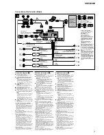
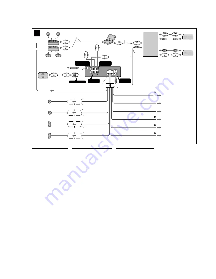
Connections (US, Canadian Model)

L

R

BUS

AUDIO IN

AUDIO OUT

REAR

FRONT

AUX IN

Schéma de raccordement (

3

)

1

À un point métallique de la voiture

Branchez d‘abord  le fil  de masse noir  et, ensuite,  les fils d‘entrée
d‘alimentation jaune 

et 

rouge.

2

Vers le fil de commande de l‘antenne électrique ou le fil
d‘alimentation de l‘amplificateur d‘antenne
Remarques

• Il n'est pas nécessaire de raccorder  ce fil  s'il n'y a pas

d'antenne électrique ni d'amplificateur d'antenne, ou avec
une antenne  télescopique  manuelle.

• Si votre voiture est équipée d'une antenne FM/AM intégrée

dans la vitre  arrière/latérale,  voir  “Remarques  sur les fils  de
commande et d'alimentation”.

3

Au niveau du AMP REMOTE IN de l’amplificateur de
puissance en option

Ce raccordement  s’applique  uniquement  aux  amplificateurs.  Le
branchement de tout autre système risque d’endommager
l’appareil.

4

Vers le cordon de liaison d’un téléphone de voiture

5

Vers le connecteur du signal d’éclairage de la voiture

Raccordez d‘abord  le  fil  de  masse noir  à un  point  métallique  de
la voiture.

6

À la borne +12 V qui est alimentée quand la clé de contact
est sur la position accessoires
Remarques

• S'il n'y  a pas de position  accessoires, raccordez la borne

d'alimentation  (batterie) +12 V qui est alimentée en
permanence.
Raccordez d‘abord  le  fil  de  masse noir  à un  point  métallique
de la voiture.

• Si votre voiture est équipée d'une antenne FM/AM intégrée

dans la vitre  arrière/latérale,  voir  “Remarques  sur les fils  de
commande et d'alimentation”.

7

À la borne +12 V qui est alimentée en permanence

Raccordez d‘abord  le  fil  de  masse noir  à un  point  métallique  de
la voiture.

Remarques sur les fils de  commande et  d'alimentation

• Le fil  de  commande  de  l’antenne  électrique  (bleu)  fournit  une

alimentation de 

12 

CC 

lorsque vous 

mettez la 

radio sous

tension.

• Lorsque votre voiture est équipée d’une antenne FM/AM intégrée

dans la vitre  arrière/latérale,  raccordez  la sortie  de commande  de
l’antenne (bleu) ou l’entrée d’alimentation  des accessoires 

(rouge)

à la borne  de l’amplificateur  d’antenne  existant.  Pour plus de
détails, consultez votre détaillant.

• Une antenne  électrique  sans boitier  de relais ne peut  pas être

utilisée avec cet appareil.

Raccordement pour la conservation de la mémoire

Lorsque le fil d’entrée d’alimentation jaune est raccordé, le circuit
de la mémoire est alimenté en permanence  même si la clé de
contact est sur la position  d’arrêt.

Remarques sur le  raccordement des haut-parleurs

• Avant de raccorder les haut-parleurs, mettez l’appareil hors

tension.

• Utilisez  des haut-parleurs  ayant  une  impédance  de 4 à 8 ohms

avec une  capacité  électrique  adéquate  pour  éviter  de les
endommager.

• Ne raccordez pas les bornes du système de haut-parleur au châssis

de la voiture  et ne raccordez pas les bornes du haut-parleur  droit
à celles du  haut-parleur  gauche.

• Ne raccordez pas le câble de masse de cet appareil  à la borne

négative (–) de l’enceinte.

• N’essayez pas de raccorder  les haut-parleurs  en parallèle.
• Raccordez uniquement  des haut-parleurs  passifs. Le raccordement

de haut-parleurs  actifs (avec amplificateurs  intégrés)  aux bornes
des haut-parleurs  peut  endommager  l’appareil.

• Pour  éviter  tout  dysfonctionnement,  n’utilisez  pas les fils  des haut-

parleurs intégrés installés dans votre voiture  si l’appareil  partage
un fil  négatif  commun  (–) pour  les haut-parleurs  droit  et gauche.

• Ne raccordez  pas entre  eux  les cordons  des haut-parleurs  de

l’appareil.

Remarque sur le raccordement

Si les enceintes  et  l’amplificateur  ne  sont  pas raccordés
correctement, le message “Failure”  s’affiche. Dans ce cas, 

assurez-

vous que les enceintes et l’amplificateur  sont bien raccordés.

3

BUS AUDIO  IN

/AUX IN

*

5

Source selector
(not supplied)
Sélecteur de source
(non fourni)
Selector de fuente
(no suministrado)

XA-C30

2

6

7

4

AMP REM

ANT REM

4

Max. supply current 0.3 A
Courant max.  fourni  0,3 A
Corriente máx. de alimentación de 0,3 A

Fuse (10  A)
Fusible (10  A)
Fusible (10  A)

Red
Rouge
Rojo

Yellow
Jaune
Amarillo

Black
Noir
Negro

Blue
Bleu
Azul

Blue/white striped
Rayé bleu/blanc
Con rayas azules y  blancas

White
Blanc
Blanco

Green
Vert
Verde

Purple
Mauve
Morado

White/black striped
Rayé blanc/noir
Con raya  blanca/negra

Gray/black striped
Rayé gris/noir
Con raya  gris/negra

Green/black striped
Rayé vert/noir
Con raya  verde/negra

Purple/black striped
Rayé mauve/noir
Con raya  violeta/negra

BUS

CONTROL IN

AUDIO OUT

FRONT

Gray
Gris
Gris

AUDIO OUT

REAR

Supplied with  the  CD/MD  changer
Fourni avec le changeur de CD/MD
Suministrado con el cambiador de CD/MD

3

Left
Gauche
Izquierdo

Right
Droit
Derecho

Left
Gauche
Izquierdo

Right
Droit
Derecho

Light blue
Bleu ciel
Azul celeste

Max. supply current 0.1 A

Courant d’alimentation  max.  0,1 A

Corriente máx. de alimentación de 0,1 A

ATT

1

SUB OUT (MONO)

*

1

Diagrama de conexión (

3

)

1

A una superficie metálica del automóvil

Conecte primero  el cable de puesta a masa negro,  y después los
cables amarillo  y rojo  de entrada  de alimentación.

2

Al cable de control de la antena motorizada o al cable de
fuente  de alimentación del amplificador de antena
Notas

• Si no  se dispone  de  antena  motorizada  ni  de  amplificador  de

antena, o se utiliza una antena telescópica accionada
manualmente, no será necesario conectar este cable.

• Si el automóvil  incorpora  una antena  de FM/AM en el cristal

trasero o lateral,  consulte “Notas sobre los cables de control  y
de fuente de alimentación”.

3

Para conectar a AMP REMOTE IN del amplificador de
potencia opcional

Esta conexión  es sólo  para  amplificadores.
La conexión  de  cualquier  otro  sistema puede  dañar  la  unidad.

4

Al cable de interfaz  de un teléfono  para automóvil

5

A una señal de iluminación del automóvil

Asegúrese de conectar primero  el cable de tierra  negro  a una
superficie metálica del automóvil.

6

Al terminal de alimentación de +12 V que recibe energía en
la posición de accesorio del interruptor  de la llave de
encendido
Notas

• Si no  hay  posición  de  accesorio,  conéctelo  al  terminal  de

alimentación (batería) de +12 V que recibe energía sin
interrupción.
Asegúrese de conectar  primero  el cable de tierra  negro  a una
superficie metálica del automóvil.

• Si el automóvil  incorpora  una antena  de FM/AM en el cristal

trasero/lateral, consulte “Notas sobre los cables de control y de
fuente de alimentación”.

7

Al terminal de alimentación de +12 V que recibe energía sin
interrupción

Asegúrese de conectar primero  el cable de tierra  negro  a una
superficie metálica del automóvil.

Notas sobre los cables de control y de fuente  de alimentación

• El conductor  de control  de la antena  motorizada  (azul) suministrará

+ cc 12 V cuando  conecte la alimentación  del sintonizador.

• Si el automóvil  dispone de una antena  de FM/AM  incorporada  en el

cristal trasero  o lateral,  conecte el cable de control  de antena
motorizada  (azul) o el cable de entrada  de alimentación  auxiliar
(rojo)  al terminal  de alimentación  del amplificador  de antena
existente. Para obtener información  detallada, consulte a su
proveedor.

• Con esta unidad  no  es posible  utilizar  una  antena  motorizada  sin

caja de relé.

Conexión para protección de la memoria

Si conecta el conductor  de entrada  amarillo,  el circuito  de la memoria
recibirá siempre alimentación,  aunque ponga la llave de encendido
en la posición OFF.

Notas sobre la conexión de los altavoces

• Antes de conectar los altavoces, desconecte la alimentación  de la

unidad.

• Utilice  altavoces con una impedancia  de 4 a 8 

 con la capacidad de

potencia adecuada para evitar que se dañen.

• No conecte los terminales  de altavoz  al chasis del automóvil,  ni

conecte los terminales  del altavoz  derecho con los del izquierdo.

• No conecte el cable de puesta a masa de esta unidad al terminal

negativo (–) del altavoz.

• No intente  conectar los altavoces en paralelo.
• Conecte solamente  altavoces pasivos. Si conecta altavoces activos

(con amplificadores  incorporados)  a los terminales  de altavoz,
puede dañar la unidad.

• Para evitar  fallos  de funcionamiento,  no utilice  los cables de altavoz

incorporados instalados en el automóvil  si su unidad comparte un
cable negativo común (–) para los altavoces derecho e izquierdo.

• No conecte los cables de altavoz  de la unidad  entre  sí.

Nota sobre la conexión

Si el altavoz  y el amplificador  no están conectados correctamente,
aparecerá “Failure”  en la pantalla.

 Si es así, compruebe  la

conexión  de ambos dispositivos.

Orange/white striped
Rayé orange/blanc
Con rayas naranjas y  blancas

5

ILLUMINATION

*

4

*

1

*

1

RCA pin  cord  (not  supplied)
Cordon à broche RCA (non fourni)
Cable con terminales RCA (no
suministrado)

*

2

Supplied with  XA-C30
Fourni avec le XA-C30
Suministrado con el  XA-C30

*

3

Auxiliary optional equipment such as
portable DVD player (not supplied)
Appareil auxiliaire en option,  par
exemple un lecteur de DVD (non
fourni)
Equipo opcional auxiliar  como un
reproductor de DVD portátil  (no
suministrado)

*

4

Supplied with  the  auxiliary  equipment
Fourni avec l’appareil  auxiliaire
Suministrado con el  equipo  auxiliar

*

5

Be sure to  match the  color-coded code
for audio to the appropriate jacks from
the unit. If you connect an optional CD/
MD unit, you cannot use AUX IN
terminal.
Veillez à faire correspondre le code
couleur audio  aux  fiches de  l’appareil.
Si vous raccordez un  appareil  CD ou
MD en option, vous ne pouvez pas
utiliser la borne AUX  IN.
Asegúrese de  hacer  coincidir el  código
codificado con colores para  audio  con
las tomas apropiadas de la unidad.

 Si

conecta una  unidad  de  CD/MD
opcional, no podrá utilizar el terminal
AUX IN.

*

2

from car antenna
à partir de l’antenne de la voiture
desde la  antena  del  automóvil

*

3

Connection diagram (

3

)

1

To a metal surface of the car

First connect the black ground lead, then connect
the yellow and red power input leads.

2

To the power antenna control lead or power
supply lead of antenna booster amplifier

Notes

• It is not necessary to connect this lead if there is no

power antenna or antenna booster, or with a
manually-operated telescopic 

antenna.

• When your car has a built-in  FM/AM antenna  in

the rear/side glass, see “Notes  on the control  and
power supply leads.”

3

To AMP REMOTE IN of an optional power
amplifier

This connection  is only  for  amplifiers.  Connecting
any other system may damage the unit.

4

To the interface cable of a car telephone

5

To a car’s illumination signal

Be sure to connect the black ground  lead to a metal
surface of the car.

6

To the +12 V power terminal which is energized
in the accessory position of the ignition key
switch

Notes

• If there  is no accessory position, connect to the +12

V power  (battery)  terminal  which  is energized  at
all times.
Be sure to  connect  the  black  ground  lead  to  a
metal surface of the car.

• When your car has a built-in  FM/AM antenna  in

the rear/side glass, see “Notes  on the control  and
power supply leads.”

7

To the +12 V power terminal which is energized
at all times

Be sure to connect the black ground  lead to a metal
surface of the car.

Notes on the  control and power  supply leads

• The power  antenna  control  lead  (blue)  su12 V

DC when  you  turn  on  the  tuner.

• When your car has built-in  FM/AM antenna  in the rear/

side glass, connect  the  power  antenna  control  lead
(blue) or the accessory power input lead (red) to the
power terminal of the existing antenna booster. For
details, consult your dealer.

• A  power  antenna  without  relay  box  cannot  be used

with this unit.

Memory hold connection

When the yellow  power  input  lead is connected, power
will always be supplied to the memory circuit even when
the ignition  key is turned  off.

Notes on speaker connection

• Before connecting  the speakers, turn the unit  off.
• Use speakers with  an impedance of 4 to 8 ohms, and

with adequate power handling capacities to avoid its
damage.

• Do not connect the speaker terminals to the car

chassis, or connect the terminals of the right  speakers
with those of the left speaker.

• Do not connect the ground  lead of this unit  to the

negative (–) terminal of the speaker.

• Do not attempt  to connect the speakers in parallel.
• Connect only passive speakers. Connecting  active

speakers (with  built-in  amplifiers)  to  the  speaker
terminals may damage the unit.

• To avoid a malfunction,  do not  use the built-in  speaker

wires installed  in your car if the unit  shares a common
negative (–) lead for the right and left speakers.

• Do not connect the unit’s  speaker cords to each other.

Note on connection

If speaker and amplifier  are not  connected  correctly,
“Failure” appears 

in 

the 

display. In 

this 

case, 

make 

sure

the speaker and amplifier  are connected correctly.

Summary of Contents for CDX-M800

Page 1: ...l to noise ratio 67 dB stereo 69 dB mono Harmonic distortion at 1 kHz 0 5 stereo 0 3 mono Separation 35 dB at 1 kHz Frequency response 30 15 000 Hz AM US Canadian model Tuning range 530 1 710 kHz Antenna terminal External antenna connector Intermediate frequency 10 7 MHz 450 kHz Sensitivity 30 µV SPECIFICATIONS MW LW AEP UK E model Tuning range MW 531 1 602 kHz LW 153 279 kHz Aerial terminal Exter...

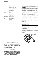
Page 2: ...ded in the repair parts The flexible board is easily damaged and should be handled with care NOTES ON LASER DIODE EMISSION CHECK The laser beam on this model is concentrated so as to be focused on the disc reflective surface by the objective lens in the optical pick up block Therefore when checking the laser diode emission ob serve from more than 30 cm away from the objective lens Notes on Chip Co...

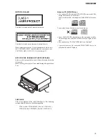
Page 3: ...nd NOTE FOR THE OPENING OF THE FRONT PANEL In this set the front panel is lowered to below the bottom face when it is opened When servicing the set place it on a stand having a height of about 2 cm AEP UK E model This label is located on the bottom of the chassis This label is located on the drive unit s internal chassis When replacing the chassis T of mechanism deck which have the CAUTION LABEL a...

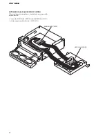
Page 4: ...SITION When repairing or servicing this set connect the jig extension cable as shown below Connect the MAIN board CNP301 and the SERVO board CN1 with the extension cable Part No J 2502 062 1 CDX M800 MAIN BOARD CNP301 SERVO BOARD CN1 ...

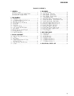
Page 5: ...Assy 17 3 6 Cam R 17 CDX M800 4 DIAGRAMS 4 1 IC Pin Descriptions 18 4 2 Block Diagram CD Section 21 4 3 Block Diagram Tuner Section 22 4 4 Block Diagram Display Section 23 4 5 Circuit Boards Location 24 4 6 Schematic Diagram CD Mechanism Section 25 4 7 Printed Wiring Boards CD Mechanism Section 26 4 8 Printed Wiring Boards Main Section 28 4 9 Schematic Diagram Main Section 1 2 30 4 10 Schematic Di...

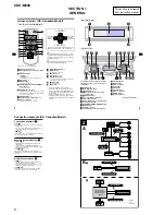
Page 6: ...elect rightwards SECTION 1 GENERAL This section is extracted from instruction manual US Canadian Model Connection example US Canadian Model 5 The buttons on the unit share the same functions as those on the card remote commander a OPEN button 9 b Main display window c IMAGE button 20 d qf Receptor for the card remote commander e qs RESET button 8 f OFF Stop Power off button 1 g SCRL scroll button ...

Page 7: ...Siel automóvil incorpora una antena de FM AM en el cristal trasero lateral consulte Notas sobre los cables de control y de fuente de alimentación 7 Al terminal de alimentación de 12 V que recibeenergía sin interrupción Asegúrese de conectar primero el cable de tierra negro a una superficie metálica del automóvil Notas sobreloscablesde control y de fuente de alimentación El conductor de control de ...

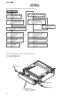
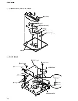
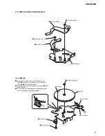
Page 8: ...Y Page 9 2 7 CHASSIS T SUB ASSY Page 11 2 8 LEVER SECTION IN SELF SW BOARD Page 12 2 10 SHAFT ROLLER ASSY LOAD SW BOARD Page 13 2 11 FLOATING BLOCK ASSY Page 13 2 12 OPTICAL PICK UP BLOCK Page 14 SET 2 9 SERVO BOARD Page 12 2 5 MAIN BOARD Page 10 2 6 HEAT SINK Page 11 2 3 SUB PANEL CD SUB ASSY Page 9 2 4 MOTOR BLOCK ASSY CAM R ASSY Page 10 1 screw panel flexible board 3 4 front panel assy Take car...

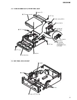
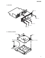
Page 9: ...6x6 3 PTT 2 6x4 5 CD mechanism block 7 bracket CD 6 PTT 2 6x6 8 tension spring flexible flexible board 9 slider flexible slider flexible 0 cover flexible qa CNP909 Note When installing the flexible board make the board slack as illustrated qs front panel assy 4 sub panel CD sub assy 2 claws 1 CNP805 3 claws ...

Page 10: ... phase alignment between cams L and R see page 15 and 17 2 5 MAIN BOARD 1 PTT 2 6x6 4 PTT 2 6x6 5 motor block assy 2 cam R assy 3 CNP902 A Note Install the cam R assy with the cam fully rotated in the direction of the arrow A 4 PTT 2 6x6 ground point 3 PTT 2 6x6 ground point 1 PTT 2 6x6 5 MAIN board 2 PTT 2 6x6 ...

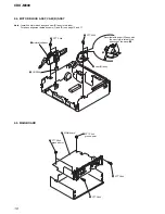
Page 11: ...11 CDX M800 2 6 HEAT SINK 2 7 CHASSIS T SUB ASSY 5 heat sink 2 PTT 2 6x6 4 PTT 2 6x6 3 PTT 2 6x12 1 PTT 2 6x6 4 chassis T sub assy 3 P 2x3 2 P 2x3 1 Unsolder the lead wires black red white ...

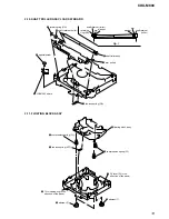
Page 12: ...s 2 IN SELF SW board 7 lever L 3 tension spring LR 6 lever R 5 guide disc 1 special screw 6 special screws 1 CN3 2 Removal the solders 4 P 2x3 5 loading motor assy 8 SERVO board 7 special screw 9 FLEXIBLE board optical pick up block 3 Unsolder the lead wires black yellow ...

Page 13: ... roller 5 shaft roller assy 6 special screw 7 LOAD SW board retaining ring RA arm arm washer washer shaft retainer roller shaft retainer roller 1 tension spring KF1 7 compression spring FL 6 floating block assy 8 compression spring FL 4 Fit lever D in the direction of the arrow 2 damper T 3 damper T 5 Turn loading ring in the direction of the arrow ...

Page 14: ...14 CDX M800 2 12 OPTICAL PICK UP BLOCK 1 P 2x3 4 screw 5 plate spring feed 6 shaft feed assy 2 sled motor assy 3 optical pick up block ...

Page 15: ...arm B L assy in the direction of the arrow A and the arm A L assy in the direction of the arrow B fully full open state 2 Align the hole large on the cam L with part C and install the cam 4 Turn the cam L clockwise and counterclockwise to verify that both the arms are operated 4 type E stop ring 1 5 2 type E stop ring 1 5 1 arm B L assy 3 arm A L assy bracket L assy ...

Page 16: ... touch the SW board SW900 1 Input 9V DC to the motor terminal until the cam L stops rotating Take care to avoid overload of the motor 2 Verify that the arm A L assy and arm B L assy are positioned as shown below full open 3 PTT 2 6x6 4 PTT 2 6x6 5 PTT 2 6x6 2 motor block SWITCH board SW900 cam L A motor GND arm B L assy arm A L assy DC 9V B ...

Page 17: ...full open state 2 Align the hole large on the cam R with part C and install the cam 4 Turn the cam R clockwise and counterclockwise to verify that both the arms are operated bracket R assy 3 arm A R assy 4 type E stop ring 1 5 2 type E stop ring 1 5 1 arm B R assy 3 type E stop ring 1 5 5 oil damper 6 screw P 2x4 cam R B A C arm B R assy hole large line arm A R assy ...

Page 18: ... output 21 FLW IN I OSC frequency shift signal for DC DC conv 22 NCO O Not used Open 23 SA CLK O Spectrum analyzer clock signal output 24 TEL ATT I telephone mute detect signal input 25 ATT O Mute signal output 26 VOL ATT O Electronic volume mute signal output 27 I2C CKO O Tuner E volume BUS clock output 28 I2C SIO O Tuner E volume BUS data output 29 UNI SO O SONY BUS data output 30 UNI SI I SONY ...

Page 19: ...input 73 TU ATT IN I Tuner mute control signal input 74 CLOSE SW I Front panel close detect signal input 75 OPEN SW I Front panel open detect signal input 76 I DET I Front panel current detect signal input 77 MOT O Front panel open close control signal output 78 MOT O Front panel open close control signal output 79 ROMC EN I ROM correction enable signal input 80 QUALITY I Tuner noise detect signal...

Page 20: ...20 NC O Connecting to pin 17 21 LAT O FL data LAT output 22 BK O FL BK output 23 GCP2 O FL GCP2 outpit 24 NC O Not used Open 25 GCP1 O FL GCP1 output 26 NC O Not used Open 27 GCP4 O FL GCP4 output 28 GCP3 O FL GCP3 output 29 SYS SO O Main BUS data output 30 SYS SI I CPU BUS data input 31 SYS CLK O Main BUS clock input 32 NC O Not used Open 33 FL DAT1 O FL serial data output 34 NC O Not used Open 3...

Page 21: ...WN X1 16 9344MHz OPTICAL PICK UP KSS 721A I V CONV CDL CD TSTB CD A0 CD TSO CD TSI CD TCKO CD RST 59 CD XTAL EN CD RFOK CD D SW CD IN SW CD SELF SW CD LIMIT CD LM LO CD LM EJ R CH TUNER SECTION A 23 24 M M M LOUT ROUT PACK TSTB TSI TSCK SI RFOK SO SCK STB AO XTALEN RST A C B D E F PD LD B D A C E F PD A 5V LD APC FCS FCS TRK TRK SL SL SP SP LD LD FOCUS COIL TRACKING COIL FD TD SD MD LOAD EJECT SYS...

Page 22: ...3 SA CLK Q171 Q181 Q470 12 5 3 11 2 4 16 22 25 34 30 37 33 31 9 7 29 27 6 20 35 POWER AMP POWER SUPPLY IC201 SW1 10V AU 8V 5V DR 6V A 5V AU 5V D 5V SW2 VP2 VP1 VP SDA SCL STB DIAG DISP B AU8V U COM MECHA SERVO CNP101 FL FL RL RL AMP REM ANT REM ATT BATT ILL ACC TEST FR 5 6 4 10 2 9 1 12 3 11 FR RR RR 19 17 18 13 16 14 7 15 X301 32 768kHz X302 6MHz R CH BATT ILLUMI CHECK Q907 AU 8V 5V REG Q501 TU 5...

Page 23: ...T 78 I DET 76 OPEN SW 75 CLOSE SW 74 OPEN KEY 90 SYSTEM CONTROL IC303 3 3 IC302 RESET MT B MT B BATT 1 2 3 MOTOR B REG IC306 IR RECEIVE IC62 IR RECEIVE IC503 7 7 1 1 KEY IN0 85 KEY IN1 84 RC IN1 70 RC IN0 86 KEY ACK2 87 KEY ACK0 88 KEY ACK1 89 SW501 RESET DIMMER CONTROL Q905 FL POWER CONTROL Q801 802 BATT BATT LED CONTROL Q903 904 DC DC CONVERTER IC800 KEY IN MATRIX FL 900 T800 FLVDD FL BATT DET Q...

Page 24: ...l capacitors are in µF unless otherwise noted pF µµF 50 WV or less are not indicated except for electrolytics and tantalums All resistors are in Ω and 1 4 W or less unless otherwise specified indicates tolerance f internal component C panel designation A B Line Power voltage is dc 14 4V and fed with regulated dc power supply from ACC and BATT cords Voltages are taken with a VOM Input impedance 10 ...

Page 25: ...R21 R22 TP34 TP35 TP36 TP46 TP37 TP38 TP39 TP40 TP41 TP42 TP43 TP44 TP45 CN1 R18 R19 R20 R17 TP66 TP62 TP47 TP63 TP48 TP49 TP64 TP50 TP51 TP52 TP68 TP53 TP69 TP54 TP70 TP55 TP71 TP56 TP72 TP57 TP73 TP58 TP74 TP59 TP75 TP60 TP76 TP61 X1 SW3 SW4 CN13 Q1 C18 IC2 IC1 TP1 TP5 C44 C40 C1 C5 C3 C6 C15 C16 C41 C27 C45 C34 C29 C25 C36 C38 C35 C24 C30 C22 C21 SW5 Refer to page 24 for Waveforms 4 6 SCHEMATIC...

Page 26: ...26 26 CDX M800 4 7 PRINTED WIRING BOARDS CD MECHANISM SECTION Refer to page 24 for Circuit Boards Location 1 A B C D E F G H I J 2 3 4 5 6 7 8 9 10 11 12 13 14 C N 2 ...

Page 27: ...P17 TP20 TP42 TP19 TP28 TP90 C41 TP29 C44 TP73 TP32 TP48 TP71 TP51 TP49 TP52 TP55 TP75 TP53 TP56 TP43 TP58 TP61 TP74 TP68 TP80 TP7 TP62 TP91 TP63 C40 TP66 TP64 TP69 TP72 TP50 TP26 TP3 TP59 TP76 TP18 TP89 TP30 R8 R9 R5 R7 R12 R14 R15 R10 R17 R18 R19 R20 R22 FB1 TP92 C3 C5 C6 C8 C9 C10 C11 C13 C14 C16 C18 C19 C24 C25 C29 C34 C36 C38 C35 C21 C22 C30 C23 C1 C27 R21 TP47 C15 C20 TP35 TP23 C17 TP82 TP44...

Page 28: ...Q305 I 9 Q306 H 10 Q307 G 10 Q380 I 8 Q401 F 5 Q402 E 5 Q408 E 2 Q470 D 3 Q501 E 1 Q801 I 4 Q802 H 4 Q907 D 8 Q914 E 11 Q915 F 10 Q916 E 11 1 A B C D E F G H I J 2 3 4 5 6 7 8 9 10 11 12 13 14 C470 R478 R364 CNP909 IC502 IC401 C903 R346 R350 R372 R373 C319 C318 D828 D829 R921 D827 D826 R910 D831 C216 D305 R325 R206 R205 C601 R314 R420 R204 D825 R421 C323 C208 C218 C809 C810 R112 C802 IC800 R324 C2...

Page 29: ...337 C928 R106 R101 R401 R108 L303 R446 C205 R439 R504 Q401 R804 R365 C508 R806 D501 R521 D118 C317 R313 R949 Q408 R424 C420 C501 D802 C522 C442 R505 R866 C506 C505 R502 C315 FB501 R501 R911 R322 C104 R442 C105 R441 D905 Q916 R343 R366 FB102 C509 R445 C201 D907 R410 R912 R811 Q802 C199 D122 R408 R807 R327 D804 R833 Q915 R402 R331 C331 R510 R511 D832 D820 C332 R342 R802 R381 D117 D116 D115 D114 D113...

Page 30: ...C218 C226 C223 C221 C215 C212 R401 C402 C401 C423 C424 C426 C427 C430 C429 C428 C431 C418 C278 C178 C288 C242 C188 C142 C442 C501 C433 C435 C434 R415 C425 R414 C422 C432 C420 C419 Q501 C502 C206 C207 D118 C104 D119 C105 Q103 C102 CN401 CN503 CNP101 F901 R478 C523 C522 R520 C521 C520 R518 C528 C527 C526 C525 R521 C524 C506 C503 C505 TUX501 PJ401 R445 R446 R442 R441 R443 R439 R444 R440 R272 R282 R17...

Page 31: ...811 R866 R812 CNJ101 R346 R372 R373 R325 C303 R371 R341 R340 C321 C338 C341 C335 R368 R369 CNP902 M601 SW900 CNP301 R313 R908 C309 R909 L302 R311 R906 R361 R912 R902 R312 JR300 R366 R343 JR302 JR301 Q101 R305 R317 R304 R310 R377 R307 FB301 FB302 R302 C318 C322 IC800 T800 Q915 R332 C306 C101 Q305 R803 C930 C305 IC303 R323 R322 C323 C315 C316 R911 FB303 R381 R360 R306 R907 R314 R308 R309 R301 IC302 ...

Page 32: ...38 R509 R538 Q504 R532 R531 D514 D507 SW501 D506 Q503 D512 C535 R535 R536 R537 CN502 C541 C513 4 11 PRINTED WIRING BOARD SUB SECTION Refer to page 24 for Circuit Boards Location Page 29 Ref No Location D506 B 10 D507 B 6 D511 C 8 D512 C 8 D513 E 13 D514 C 10 IC503 B 12 Q503 C 9 Q504 B 9 Semiconductor Location Ver 1 1 ...

Page 33: ...ock Diagrams Note Voltage is dc with respect to ground under no signal detuned condition no mark FM Page 31 IC B D D506 D507 D511 D512 D513 D514 IC503 Q503 Q504 R531 R532 R533 CN502 C536 C540 C533 C539 C538 R509 R538 C537 FB503 SW501 CN501 C535 R537 C541 R536 R534 R535 Ver 1 1 ...

Page 34: ...R984 C909 C910 LED909 C961 C983 IC301 R939 R929 R928 FB907 Q904 Q903 FB908 FB909 FB911 FB912 FB913 C901 R906 FB917 FB904 R994 R964 R967 R968 D908 R944 D902 FB901 R985 C911 R940 FB906 R941 FB925 FB903 FB926 FB905 C914 R947 FB902 R982 D901 R965 FB971 S931 FB914 R969 C905 IC62 C903 R991 FB915 C902 R992 R916 FB916 C913 X301 FB923 FB922 FB920 FB921 FB60 R987 R986 S932 C970 LED931 R970 C963 C912 C973 IC...

Page 35: ...909 C911 R939 C962 C983 Q905 R990 LCD2 FB911 FB907 FB908 FB909 FB904 FB901 FB902 FB903 FL900 FB60 FB914 FB915 FB916 FB925 FB917 FB920 FB921 FB923 FB922 FB906 FB905 FB912 FB913 FB926 C960 C963 C973 R946 R952 R951 R956 R953 R958 R957 R961 R959 R962 R994 R988 FL910 FL924 FL919 FL918 R970 C961 C920 C921 C922 D913 D911 D912 D910 D914 D917 D918 D919 D915 D916 CNP908 D921 D920 R989 R964 R965 R967 IC2 R94...

Page 36: ...D CONVERTER MEMORY PROCESSOR COMPARATOR IC502 SAA6588T MAIN Board 1 2 IC301 BA8270F MAIN Board 2 2 1 FWD 2 REV LOADING PRE FWD REV 3 LDCONT 6 IN2 7 PREVCC 8 POWVCC VOL VOL IN1 4 PS LEVEL SHIFT LEVEL SHIFT LEVEL SHIFT POWER SAVE CH1 4 MUTE X3 9 10 11 VO2 12 VO2 13 VO1 14 VO1 5 BIAS OPIN4 OPIN4 OPIN3 OPOUT3 MUTE POWVCC GND OPIN3 OPOUT4 VO3 VO3 VO4 VO4 7 5k 7 5k 16k 16k 7 5k 7 5k 16k 16k 10k 10k 10k ...

Page 37: ... 2 4 6 8 10 12 14 16 18 20 22 24 26 28 30 32 34 36 TAB FL FL RL RL IN_RL SGND IN_RR RR RR FR FR DIAG SW2 SW1 SERVO MECHA VP U COM SDA SCL VP2 PGND3 SVR IN_FL IN_FR ACGND PGND2 VP1 STB PGND1 RST CRES AU8V GND DISP B CBU FL RL RR VP FR I2C BUS 16 1 2 3 4 5 6 7 8 15 14 13 11 10 12 9 VIN LIN GND VSTAB VCC NC NC VPO NC GND A VIN VAGC INS VCO NC GND INPUT SLAGE 320kHz AGC 320kHz 500kHz PULSE COUNTER PUL...

Page 38: ...FILTER2 MIXER MIXER SUB WOOFER FILTER HIGH PASS FILTER LOUDNESS FADER II2CBUS SOFT STEP FADER HIGH PASS FILTER2 37 ACOUTSW 36 ACINSW 35 ACOUTR 34 NC 9 10 SOFT STEP FADER SOFT STEP FADER ZERO CROSS SPECTRUM ANALIZER FILOL 26 AC2OUTL 27 AC2INL 28 VREFOUT 30 VDD 29 13 SCL SAIN 12 SDA 14 18 FILOR 19 AC2OUTR 20 AC2INR 22 OUTRF 40 41 42 43 44 AUXL MDR MDL AMR AML 38 CREF 39 NC 1 2 3 4 5 6 7 14 13 12 11 ...

Page 39: ... mean standardized parts so they may have some difference from the original one Color Indication of Appearance Parts Example KNOB BALANCE WHITE RED Parts Color Cabinet s Color Accessories are given in the last of this parts list Abbreviation CND Canadian model R R 1 X 3382 819 1 PANEL CD SUB ASSY SUB US CND 1 X 3382 825 1 PANEL CD SUB ASSY SUB AEP UK E 2 1 783 268 11 CABLE FLAT FFC 11P 3 1 687 950...

Page 40: ...3 342 940 01 WASHER M 59 3 045 713 01 GEAR A 60 A 3326 298 A SWITCH BOARD COMPLETE 61 X 3378 711 4 BRACKET MOTOR ASSY 62 3 230 494 01 GEAR C 63 3 230 496 01 CAM R 64 X 3380 545 2 BRACKET R ASSY 65 3 030 909 11 DAMPER OIL 66 X 3382 823 1 ARM A R ASSY M601 X 3378 769 1 MOTOR ASSY OPEN CLOSE 2 7 685 792 09 SCREW PTT 2 6X6 S 4 7 627 553 28 SCREW PRECISION P 2X2 5 5 7 624 102 04 STOP RING 1 5 TYPE E 7 ...

Page 41: ...OINT 106 A 3274 749 A MAIN BOARD COMPLETE US CND 106 A 3274 769 A MAIN BOARD COMPLETE AEP UK E 107 1 777 246 41 CORD WITH CONNECTOR ANTENNA 108 1 790 375 32 CORD WITH CONNECTOR SUB OUT MONO F901 1 532 877 11 FUSE BLADE TYPE AUTO FUSE 10A TUX501 A 3220 887 A TUNER UNIT TUX 030 2 7 685 792 09 SCREW PTT 2 6X6 S 3 7 685 795 09 SCREW PTT 2 6X12 S not supplied F901 TUX501 not supplied not supplied 2 2 2...

Page 42: ...39 338 01 BUTTON SOURCE 163 3 248 825 01 PLATE FL GUIDE 164 3 248 791 01 BUTTON OPEN 165 3 248 789 01 BUTTON RESET DSPL 166 2 626 869 01 SCREW M2X3 SERRATION 167 1 687 952 11 FLEXIBLE BOARD 168 X 3381 646 1 BRACKET PANEL ASSY 169 A 3274 753 A DISPLAY BOARD COMPLETE US CND 169 A 3274 766 A DISPLAY BOARD COMPLETE AEP UK E 170 3 238 827 01 PLATE LCD KEY LIGHT GUIDE 171 3 238 826 01 SHEET KEY DIFFUSIO...

Page 43: ... 3 040 037 01 GUIDE DISC 210 3 040 040 03 ARM ROLLER 211 A 3283 233 A SERVO BOARD COMPLETE 212 3 221 779 02 BRACKET MOTOR 213 3 040 034 01 SPRING RA TENSION 214 3 040 042 01 WASHER 215 3 043 880 01 RING RA RETAINING 216 3 044 206 11 SCREW SPECIAL 217 1 683 284 11 FLEXIBLE BOARD 218 1 685 337 11 LOAD SW BOARD M903 A 3315 039 A MOTOR SUB ASSY LO LOADING 8 7 627 553 37 SCREW PRECISION P 2X3 TYPE3 9 7...

Page 44: ...TAINER DISC 255 3 040 054 01 WHEEL LW WORM 256 3 040 026 01 SPRING CH TENSION 257 3 040 032 01 SPRING FL COMPRESSION 258 3 040 033 01 SPRING KF1 TENSION 259 A 3307 422 A CHASSIS M COMPLETE ASSY 260 3 040 059 01 SPRING TR TENSION 261 3 040 057 01 LEVER LOCK 262 3 040 058 01 GEAR MDL 263 3 040 052 01 WHEEL U WORM 264 3 040 051 02 LEVER TR 254 251 256 257 258 260 262 261 259 252 252 252 253 263 257 D...

Page 45: ...portant le numéro spécifié 301 X 3378 480 1 CHASSIS OP ASSY including M901 302 3 040 029 01 SPRING SL TORSION 303 3 040 045 01 BASE DRIVING 304 3 040 194 01 GEAR MIDWAY 305 A 3301 983 A SHAFT FEED ASSY 306 3 040 030 01 SPRING FEED PLATE 307 1 823 641 11 CABLE FLEXIBLE FLAT 6 CORE 308 1 683 282 11 SL SW BOARD 309 3 909 607 01 SCREW 0310 8 820 165 06 OPTICAL PICK UP KSS 721A C RP M902 A 3301 985 A M...

Page 46: ...C CHIP 0 1uF 25V C922 1 164 156 11 CERAMIC CHIP 0 1uF 25V C960 1 162 908 11 CERAMIC CHIP 3PF 0 25PF 50V C961 1 162 907 11 CERAMIC CHIP 2PF 0 25PF 50V C962 1 164 156 11 CERAMIC CHIP 0 1uF 25V C963 1 165 319 11 CERAMIC CHIP 0 1uF 50V C970 1 164 156 11 CERAMIC CHIP 0 1uF 25V C973 1 165 319 11 CERAMIC CHIP 0 1uF 50V C983 1 125 837 11 CERAMIC CHIP 1uF 10 6 3V CONNECTOR CNP908 1 774 678 21 CONNECTOR FPC...

Page 47: ...218 859 11 RES CHIP 3 3K 2 1 16W R917 1 218 855 11 RES CHIP 2 2K 2 1 16W R918 1 218 851 11 RES CHIP 1 5K 2 1 16W R919 1 218 851 11 RES CHIP 1 5K 2 1 16W R920 1 218 847 11 RES CHIP 1K 2 1 16W R921 1 219 286 11 RES CHIP 680 2 1 16W R922 1 219 286 11 RES CHIP 680 2 1 16W R923 1 219 286 11 RES CHIP 680 2 1 16W R925 1 218 871 11 RES CHIP 10K 2 1 16W AEP UK E R928 1 216 829 11 METAL CHIP 4 7K 5 1 10W R9...

Page 48: ... 50V C201 1 115 467 11 CERAMIC CHIP 0 22uF 10 10V C202 1 162 923 11 CERAMIC CHIP 47PF 5 50V C203 1 124 257 00 ELECT 2 2uF 20 50V C204 1 124 234 00 ELECT 22uF 20 16V C205 1 164 156 11 CERAMIC CHIP 0 1uF 25V C206 1 125 891 11 CERAMIC CHIP 0 47uF 10 10V C207 1 125 891 11 CERAMIC CHIP 0 47uF 10 10V C208 1 162 927 11 CERAMIC CHIP 100PF 5 50V C209 1 162 927 11 CERAMIC CHIP 100PF 5 50V C210 1 164 156 11 ...

Page 49: ...5V C802 1 165 874 21 ELECT CHIP 120uF 20 6 3V C803 1 128 576 11 ELECT 100uF 20 63V C807 1 110 501 11 CERAMIC CHIP 0 33uF 10 16V C809 1 164 156 11 CERAMIC CHIP 0 1uF 25V C810 1 128 416 11 ELECT CHIP 100uF 20 16V C901 1 124 234 00 ELECT 22uF 20 16V C903 1 164 156 11 CERAMIC CHIP 0 1uF 25V C928 1 164 156 11 CERAMIC CHIP 0 1uF 25V C930 1 124 234 00 ELECT 22uF 20 16V CONNECTOR CN401 1 506 985 11 PIN CO...

Page 50: ... 8 729 920 21 TRANSISTOR DTC314TK T 146 Q305 8 729 901 00 TRANSISTOR DTC124EK Q306 8 729 216 22 TRANSISTOR 2SA1162 G Q307 8 729 901 81 TRANSISTOR 2SC2412K T 146 R Q380 1 801 806 11 TRANSISTOR DTC144EKA AEP UK E Q401 8 729 900 53 TRANSISTOR DTC114EK Q402 8 729 027 23 TRANSISTOR DTA114EKA T146 Q408 8 729 053 84 FET SSM3KO9FU T5LSONY1 Q470 8 729 920 21 TRANSISTOR DTC314TK T 146 Q501 8 729 106 68 TRAN...

Page 51: ...W R368 1 216 809 11 METAL CHIP 100 5 1 10W R369 1 216 809 11 METAL CHIP 100 5 1 10W R370 1 216 829 11 METAL CHIP 4 7K 5 1 10W R371 1 216 298 00 METAL CHIP 2 2 5 1 10W R372 1 216 809 11 METAL CHIP 100 5 1 10W R373 1 216 845 11 METAL CHIP 100K 5 1 10W R377 1 216 845 11 METAL CHIP 100K 5 1 10W R380 1 216 809 11 METAL CHIP 100 5 1 10W AEP UK E R381 1 216 845 11 METAL CHIP 100K 5 1 10W R401 1 216 017 1...

Page 52: ...C16 1 162 970 11 CERAMIC CHIP 0 01uF 10 25V C17 1 162 970 11 CERAMIC CHIP 0 01uF 10 25V C18 1 162 966 11 CERAMIC CHIP 0 0022uF 10 50V C19 1 107 826 11 CERAMIC CHIP 0 1uF 10 16V C20 1 107 826 11 CERAMIC CHIP 0 1uF 10 16V C21 1 162 970 11 CERAMIC CHIP 0 01uF 10 25V C22 1 162 970 11 CERAMIC CHIP 0 01uF 10 25V C23 1 162 970 11 CERAMIC CHIP 0 01uF 10 25V C24 1 162 970 11 CERAMIC CHIP 0 01uF 10 25V C25 ...

Page 53: ...5 1 10W SWITCH SW501 1 692 135 21 SWITCH KEYBOARD RESET A 3326 298 A SWITCH BOARD COMPLETE including SW900 MISCELLANEOUS 8 1 776 207 72 CORD WITH CONNECTOR POWER US CND E 8 1 776 527 71 CORD WITH CONNECTOR ISO POWER AEP UK 107 1 777 246 41 CORD WITH CONNECTOR ANTENNA 108 1 790 375 32 CORD WITH CONNECTOR SUB OUT MONO 167 1 687 952 11 FLEXIBLE BOARD 301 X 3378 480 1 CHASSIS OP ASSY including M901 30...

Page 54: ...S 351 X 3382 647 1 FRAME ASSY FITTING 352 X 3366 405 1 SCREW ASSY EXP FITTING AEP UK E 353 X 3382 821 1 COLLAR ASSY 354 3 934 325 01 SCREW K 5X8 TP US CND E 355 1 465 459 21 ADAPTOR ANTENNA AEP UK 356 1 776 207 72 CORD WITH CONNECTOR POWER US CND E 357 1 776 527 71 CORD WITH CONNECTOR ISO POWER AEP UK 358 3 246 471 01 KEY FRAME ...

Page 55: ...55 CDX M800 MEMO ...
Page 56: ...o the revised page Also clicking the version at the upper on the revised page allows you to jump to the next revised page Ver Date Description of Revision 1 0 2003 01 New 1 1 2003 05 Change the main sub and display boards Correction of Exploded views ECN CSA06779 CSA06821 ...

Reviews: