30
CDX-T67
5-12.
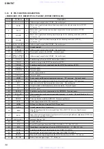
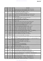
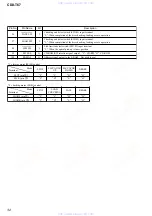
IC PIN FUNCTION DESCRIPTION
•
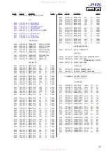
MAIN BOARD IC301 MB90473PFV-G-113-BNDE1 (SYSTEM CONTROLLER)
Pin No.
Pin Name
I/O
Description
1, 2
RAMA5, RAMA6
O
Address signal output to the S-RAM Not used (open)
3
ELVR
O
Motor drive signal (elevator down direction) output to the elevator motor drive (IC302)
“L” active *1
4
ELVF
O
Motor drive signal (elevator up direction) output to the elevator motor drive (IC302)
“L” active *1
5
LOADF
O
Motor drive signal (load chucking direction) output to the chucking motor drive (IC201)
“L” active *2
6
LOADR
O
Motor drive signal (save direction) output to the chucking motor drive (IC201)
“L” active *2
7, 8
RAMA7, RAMA12
O
Address signal output to the S-RAM Not used (open)
9
VSS
—
Ground terminal
10
RAMA14
O
Address signal output to the S-RAM Not used (open)
11
RAMWE
O
Write enable output to the S-RAM Not used (open)
12 to15
RAMA13, RAMA8,
RAMA9, RAMA11
O
Address signal output to the S-RAM Not used (open)
16
UNI SI
I
Serial data input from the SONY bus interface (IC201)
17
UNI SO
O
Serial data output to the SONY bus interface (IC201)
18
UNI CK
I
Serial data transfer clock signal input from the SONY bus interface (IC201)
19
LEDDAT
O
Not used (open)
20
LEDCLK
O
Not used (open)
21
VCC
—
Power supply terminal
22
LEDLAT
O
Not used (open)
23
CDON
O
Power supply on/off control signal output terminal “H”: power on Not used (open)
24
ELVON
O
Mechanism deck section power supply on/off control signal output “H”: power on
25
RX
I
Input terminal at the flash memory data write mode Not used (open)
26
TX
O
Output terminal at the flash memory data write mode Not used (open)
27
NC
O
Not used (open)
28
EECLK
O
Serial data transfer clock signal output to the EEPROM Not used (open)
29
FL BOOT
I
Flash memory data write control signal input terminal “L” active Not used (fixed at “H”)
Two-way data bus with the EEPROM Not used (pull down)
Power supply terminal (for A/D converter)
Reference voltage input terminal (for A/D converter)
Ground terminal (for A/D converter)
Elevator height position detection signal input from the RV301 (elevator height sensor)
(A/D input)
38, 39
KEY0, KEY1
I
Not used (fixed at “H”)
40
VSS
—
Ground terminal
41
FOK
I
Focus OK signal input from the CXD3017Q (IC401) “L”: NG, “H”: OK
42
GFS
I
Guard frame sync signal input from the CXD3017Q (IC401) “L”: NG, “H”: OK
43
SCLK
O
Serial data reading clock signal output to the CXD3017Q (IC401)
44
SENS
I
Internal status signal (sense signal) input from the CXD3017Q (IC401)
45
BUSON
I
Bus on/off control signal input from the SONY bus interface (IC201) “H”: bus on
46
BUCHK
I
Battery detection signal input “L”: battery on
www. xiaoyu163. com
QQ 376315150
9
9
2
8
9
4
2
9
8
TEL 13942296513
9
9
2
8
9
4
2
9
8
0
5
1
5
1
3
6
7
3
Q
Q
TEL 13942296513 QQ 376315150 892498299
TEL 13942296513 QQ 376315150 892498299


