background image

ICF-303/303L

– 7 –

– 8 –

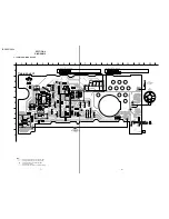
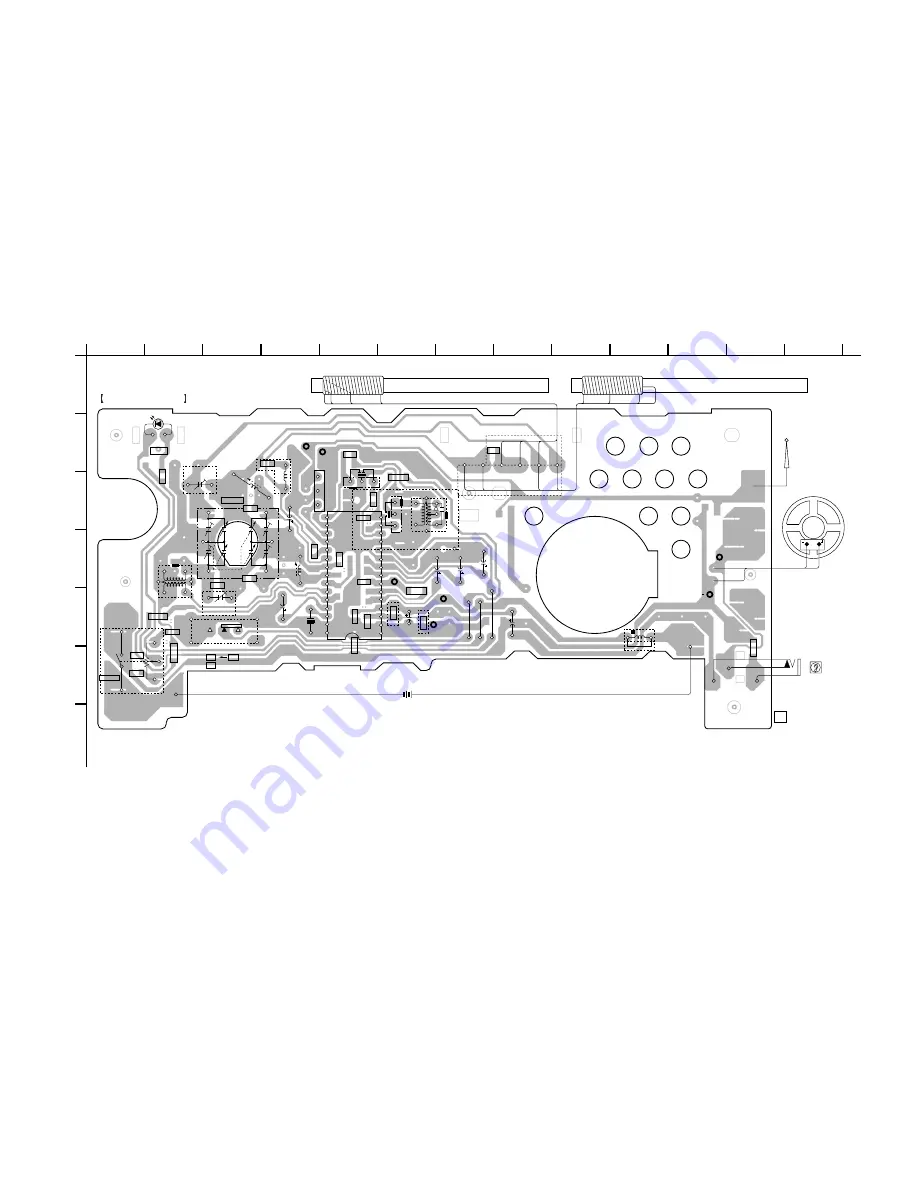
4-1. PRINTED WIRING BOARD

1

A

B

C

D

E

F

G

2

3

4

5

6

7

8

9

10

11

12

13

1-638-452-

11

MAIN BOARD

R4

C15

R6

C9

R9

C13

C17

R7

C18

C24

R2

C4

C3

C8

CF1

CT1

LW OSC

C19

C21

C23

C6

R8

C2

R3

J3

R1

J2

J4

DRY BATTERY

 SIZE "AA"

(IEC DESIGNATION R6)

2PCS,3V

C14

C16

C12

C11

C20

S1

(BAND)

LW            FM

AM

(303)

(303L)

TUNE

303L

303L

LW ANT

CT2

L2

L7

L6

ANT 1

FM TELESCOPIC

ANTENNA

SP 1

SPEAKER

WHT

RED

RED

WHT

EPJ1

(EARPHONE)

L4

CF3

C5

303L

303

303L

CT1-2

CT1-3

CT1-1

CT1-4

30

16

21

25

1

5

15

10

T1

AM IF

CF2

BPF1

IC1

-1

-2

-3

-4

         L5 
AM OSC(303)   
LW OSC(303L)

RV1-2

VOL

RV1-1

RV1

POWER

04

SHIELD PLATE

BLK

RED

BLU

BLK

BLU

BLK

RED

RED

BLU

CLEAR

CLEAR

CLEAR

LW FERRITE-ROD ANTENNA(303L)

D3

303L

303L

RF IN(+)

DET OUT

RF IN(-)

B+

GND

FM

ANT

WHT

SP(+)

SP(  )

CV1

TUNING

L1

BLK

RED

BLU

CLEAR

AM FERRITE-ROD ANTENNA(303)

L1

(303L)

(303)

1

3

Note:

X

: parts extracted from the component side.

Y

: parts extracted from the conductor side.

p

: parts mounted on the conductor side.

¢

: internal component.

b

: Pattern from the side which enables seeing.

SECTION 4

DIAGRAMS

Summary of Contents for CF-303

Page 1: ...z LW 153 255 kHz Speaker Approx 6 6 cm 2 5 8 inches dia 8 Ω Output v earphone jack minijack Power output 100 mW at 10 harmonic distortion Power requirements 3 V DC two R6 size AA batteries 3 V DC two LR6 size AA batteries Dimensions Approx 156 9 82 5 41 1 mm w h d 6 1 4 3 1 4 1 5 8 inches incl projecting parts and controls Mass Approx 309 5 g 10 9 oz incl batteries Supplied accessories Operating i...

Page 2: ... CF3 You must use same type of color marked ceramic filters in order to meet same specifications Therefore the ceramic filter must change two pieces together since it s supply two pieces in one package as a spare parts mark mark CF3 CF1 Notes on Chip Component Replacement Never reuse a disconnected chip component Notice that the minus side of a tantalum capacitor may be damaged by heat ...

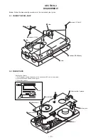
Page 3: ... 3 SECTION 1 GENERAL This section is extracted from instruction manual ...

Page 4: ...rocedure in the numerical order given 2 1 CABINET REAR ASSY 2 2 MAIN BOARD SECTION 2 DISASSEMBLY 1 screws P 2 6x12 5 screws B 1 7x4 6 lug 2 6 7 cabinet REAR assy 2 claw 3 claw 4 claw Setting the Pointer 1 Turn the gear tuning capacitor in the direction of A until it is stopped 2 Place the rack as shown in the figure 3 Mount the pointer ...

Page 5: ...el as low as possible Repeat the procedures in each adjustment several times and the frequency coverage and tracking adjustments should be finally done by the trimmer capacitors ICF 303 FM FREQUENCY COVERAGE ADJUSTMENT Adjust for a maximum reading on level meter L4 86 5 87 35 64 MHz CT1 3 109 5 108 25 MHz FM TRACKING ADJUSTMENT Adjust for a maximum reading on level meter L2 86 5 87 35 68 MHz CT1 2...

Page 6: ...EARPHONE L4 CF3 C5 303L 303 303L CT1 2 CT1 3 CT1 1 CT1 4 30 16 21 25 1 5 15 10 T1 AM IF CF2 BPF1 IC1 1 2 3 4 L5 AM OSC 303 LW OSC 303L RV1 2 VOL RV1 1 RV1 POWER 04 SHIELD PLATE BLK RED BLU BLK BLU BLK RED RED BLU CLEAR CLEAR CLEAR LW FERRITE ROD ANTENNA 303L D3 303L 303L RF IN DET OUT RF IN B GND FM ANT WHT SP SP CV1 TUNING L1 BLK RED BLU CLEAR AM FERRITE ROD ANTENNA 303 L1 303L 303 1 3 Note X par...

Page 7: ...signation U B Line H adjustment for repair Total current is measured with power on Power voltage is dc 3 V and fed with regulated dc power supply from battery terminal Voltage is dc with respect to ground under no signal detuned condition no mark FM AM or LW Voltages are taken with aVOM Input impedance 10 MΩ Voltage variations may be noted due to normal produc tion tolerances Signal path F FM Abbr...

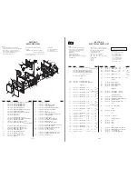
Page 8: ...UG 2 6 21 3 037 039 01 CABINET REAR BLACK 21 3 037 039 11 CABINET REAR WHITE EXCEPT EE 22 3 372 124 01 CUSHION BATTERY 23 3 037 024 01 HANDLE BLACK 23 3 037 024 11 HANDLE WHITE EXCEPT EE 24 7 685 136 19 SCREW P 2 6X12 TYPE2 N S 25 3 037 034 01 SPRING HANDLE 26 3 037 019 01 LID BATTERY CASE BLACK 26 3 037 019 11 LID BATTERY CASE WHITE EXCEPT EE 27 3 037 042 01 KNOB BAND BLACK 27 3 037 042 11 KNOB B...

Page 9: ...03 R8 1 216 295 00 SHORT 0 303L R9 1 216 043 00 RES CHIP 560 5 1 10W 303L VARIABLE RESISTOR RV1 1 241 555 11 RES VAR CARBON 50K POWER VOL SWITCH S1 1 552 370 00 SWITCH SLIDE BAND TRANSFORMER T1 1 404 341 00 TRANSFORMER IF 303 T1 1 404 355 00 TRANSFORMER IF 303L MISCELLANEOUS ANT1 1 501 247 21 ANTENNA TELESCOPIC SP1 1 529 456 11 SPEAKER 6 6cm ACCESSORIES PACKING MATERIALS 3 867 126 11 MANUAL INSTRU...

Page 10: ... allows you to jump to the revised page Also clicking the version at the upper on the revised page allows you to jump to the next revised page Ver Date Description of Revision 1 0 1999 07 New 1 1 2004 04 Taiwan model Addition IDF 303 303L ...

Reviews: