12
CFD-G55
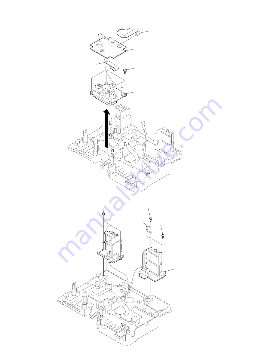
3-14. CD Block Section
(KSM-213RDP)
3-15. PDW, L-R/REG Board
1
s
crew
+BVTP 3
×
10
3
t
wo screws
+BVTP 3
×
10
4
L-R/REG board,
chassis (HS, L)
2
clamp
5
three
screws
+BVTP 3
×
10
6
PDW board,
Chassis (HS, R)
4
CD board
3
f
lexible flat cable
CNP701
2
Remove solderings
from the four points.
1
f
lexible flat cable
(from MAIN board CNP802)
6
CD block section
(KSM-213RDP)
5
f
our screws
+PWH 2.6
×
10
Summary of Contents for CFD-G55 - Cd Radio Cassette-corder
Page 26: ...26 26 CFD G55 5 10 Schematic Diagram MAIN Section 1 2 See page 34 for IC Block Diagrams ...
Page 29: ...29 29 CFD G55 5 13 Schematic Diagram AMP Section ...
Page 31: ...31 31 CFD G55 5 15 Schematic Diagram CONTROL Section ...
Page 33: ...33 33 CFD G55 5 17 Schematic Diagram POWER Section ...
Page 53: ...53 CFD G55 MEMO ...


