3
CFM-20L
SECTION 2
DISASSEMBLY
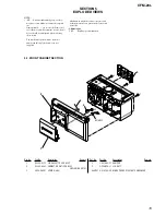
Note :
Follow the disassembly procedure in the numerical order given.
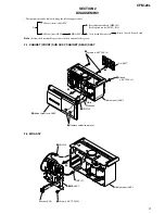
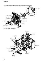
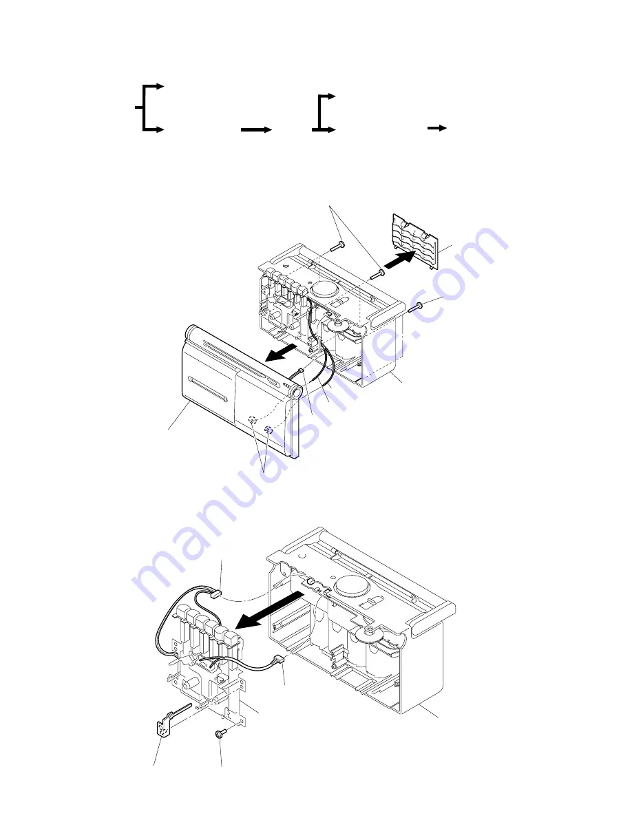
2-2. MD ASSY
• The equipment can be removed using the following procedure.
Set
Cabinet (front) sub ASSY
Cabinet (rear) ASSY
Jack board, Main board
Batt(+) board, Power board
MD ASSY
Record/playback head (HRP101),
Reel/capstan motor (M101), Belt
3
1
2
Screws (+ BVTP 3X14)
2
Screws
(+ BVTP 3X14)
4
Remove solder (two place)
5
CNP103
6
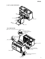
Cabinet (front) sub ASSY
Lid, BATT
Cabinet (rear) ASSY
White
White/red
3
4
CNP102
1
Screw (+ BVTP 3X10)
2
CNP101
5
MD ASSY
Bracket (VOL)
Cabinet (rear) ASSY
2-1. CABINET (FRONT) SUB ASSY, CABINET (REAR) ASSY


