4-17 (E)
CLX101ASA
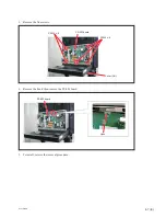
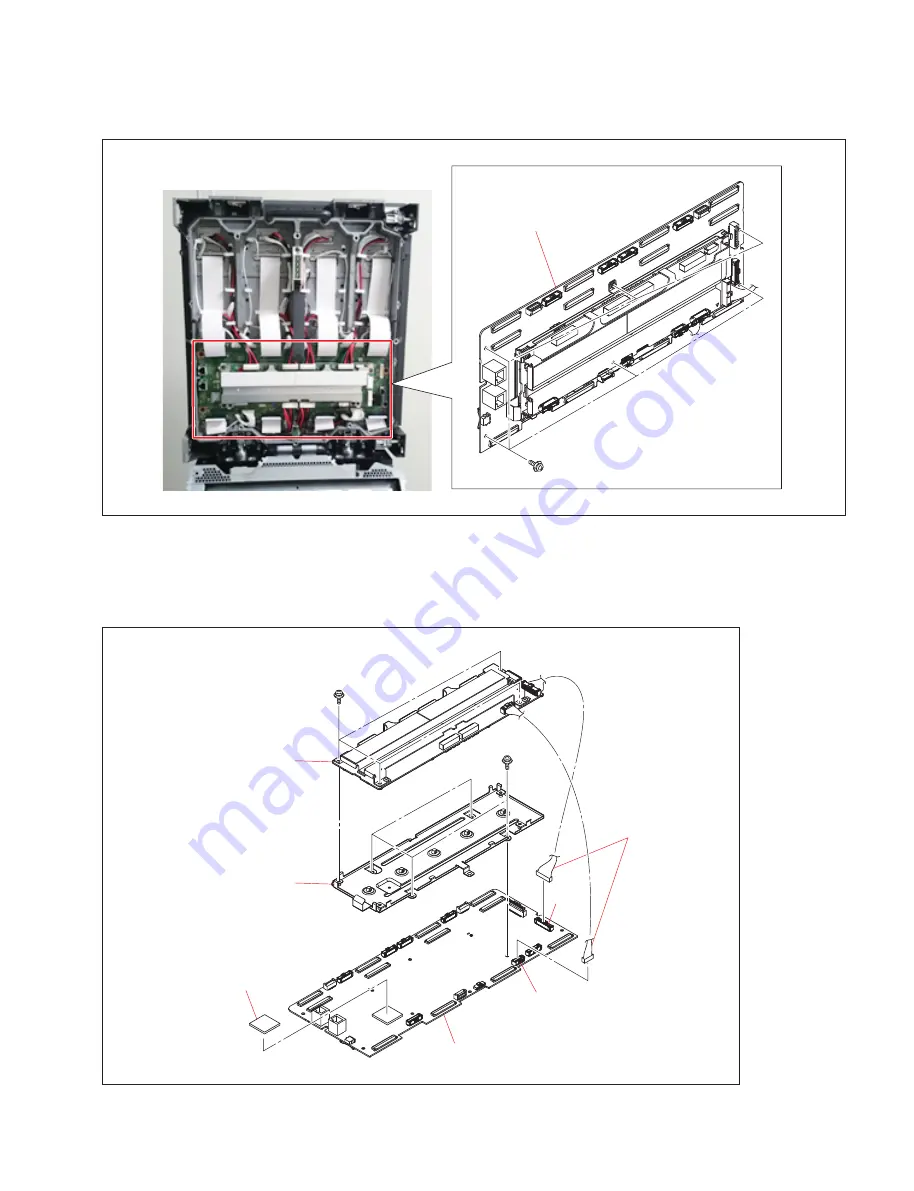
5. Remove the six screws, then remove the UP-13 board and UC-1 board integrated block.
6. Disconnect the two harnesses from the connectors (CN1507 and CN1509) on the UC-1 board.
7. Remove the four screws, then remove the UP-13 board.
8. Remove the four screws, then remove the UP bracket.
9. Peel off the radiation sheet (FPGA).
UP-13 board and UC-1 board
integrated block
PSW
3
)
8
UC-1 board
Radiation sheet (FPGA)
Harnesses
UP-13 board
UP bracket
CN1507
CN1509
PSW
3
)
8
PSW
3
)
8
Summary of Contents for CLX101ASA
Page 1: ...DISPLAY UNIT CLX101ASA SERVICE MANUAL 1st Edition Revised 2 ...
Page 6: ......
Page 40: ......
Page 84: ......
Page 86: ......
Page 98: ......
Page 100: ......
Page 102: ......
Page 103: ......
Page 104: ...Sony Corporation CLX101ASA SY CLX101ASA CN J E 9 976 961 03 Printed in Japan 2018 7 32 2016 ...


