background image

13

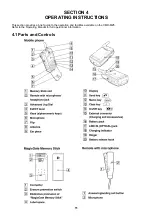
Summary of Contents for CMD-MZ5

Page 1: ...85 MHz Receive 1805 1880 MHz GSM power class Class 4 2W DCS power class Class 1 1W SIM chip Pluggable mini SIM card Display High resolution full graphics display Resolution 96 x 72 pixels Graphic Icons 5 lines x 12 normal font numeric charactors Channel spacing 200 kHz Number of channels E GSM 174 DCS 374 Frequency stability Transmit frequency drift synchronized 0 1 p p m RF output power GSM 2W DC...

Page 2: ...Design and specifications are subject to change without notice by CC Toko NOTE This device contains electrostatically sensitive components Damage can occur to these components if the appropriate handling is not adhered to ESD Handling precautions A working area in which Digital Cellular Telephones may be safely handled without undue risk of damage from electrostatic discharge must be available The...

Page 3: ...av batteri Benytt samme batteritype eller en tilsvarende type anbefalt av apparatfabrikanten Brukte batterier kasseres i henhold til fabrikantens instruksjoner VARNING Explosionsfara vid felaktigt batteribyte Använd samma batterityp eller en likvärdig typ som rekommenderas av apparattillverkaren Kassera använt batteri enligt gällande föreskrifter VAROITUS Paristo voi räjähtää jos se on virheellise...

Page 4: ...ale by itself 10 3 7 Standard Battery QN MZ5 not for sale by itself 10 3 8 Magic Gate Memory Stick 10 3 9 Headphones not for sale by itself 10 3 10 Remote with Microphone not for sale by itself 10 3 11 Optical Cable not for sale by itself 10 3 12 Carry Bag not for sale by itself 10 3 13 Analog Audio Cable not for sale by itself 10 SECTION 4 Operating Instructions 4 1 Parts and Controls 11 4 2 Basi...

Page 5: ...ase Band Block 7 2 1 Block Diagram 1 2 27 7 2 2 Block Diagram 2 2 28 7 2 3 Operational Description 29 7 3 Memory Stick Block 30 7 3 1 Block Diagram 1 2 30 7 3 2 Block Diagram 2 2 31 7 3 3 Operational Description 32 SECTION 8 Spare Parts and Accessories List 8 1 Spare Parts 33 8 2 Accessories List 34 ...

Page 6: ...RTC is powered from the main battery via its own low quiescent current regulator When the main battery is low or removed a back up battery keeps the clock alive 2 3 Vibra Alert Functionality The vibrator is a 1 3V device A general port pin of the SC1 controls the switch mode of the vibration motor It is powered through a regulator by an interface control unit If the mobile is in the phase of switc...

Page 7: ...er accessory is detected via an Interrupt This detection is only possible when the phone is powered up ID The ID pin indicates what kind of accessory is connected ACC power ACC power has different functionality with different accessories ACC power supplies will be used as a signaling pin for the Hands Free Kit In the car kit environment the ext Vbat indicates that a phone call is accepted in progr...

Page 8: ...coming call is stopped during recording sound to keep good sound quality l You can playback sound data recording onto the memory stick l The Play Settings function allows you to select how to play back such as Bass AVLS and Repeat Shuffle l Selecting the next track the previous track going forward backward and stop are available l When you receive an incoming call during playback playback is stopp...

Page 9: ... charging can take up to 3 hours but will be longer if the CMD MZ5 is switched on or if the temperature is outside the 0 C 45 C operating range Specifications Input voltage DC 12V negative ground Rated output voltage 5 0V Rated output current 500mA 3 3 AC Adapter The Power Adapter QN 2TC is a small and lightweight device It has a full Input Voltage Range from 110 240Volts Using a standard cable ma...

Page 10: ...dard Battery not for sale by itself Specifications Lithium Ion Battery A 3627 234 A QN MZ5BPS Maximum output voltage DC 4 2V Nominal output voltage DC 4 0V Capacity 620mAh 3 8 Magic Gate Memory Stick 3 9 Eearphones 1 542 459 11 not for sale by itself Ø 3 5 stereo mini plug 3 10 Remote with Microphone 1 476 509 11 not for sale by itself 3 11 Optical Cable 1 757 888 11 not for sale by itself 3 12 Ca...

Page 11: ...TION 4 OPERATING INSTRUCTIONS This section provides a brief guide to the operation and facilities available on the CMD MZ5 Refer to the Operating Manual for full operational information 4 1 Parts and Controls ...

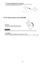
Page 12: ...12 4 2 The Basic Features of the CMD MZ5 ...

Page 13: ...13 ...

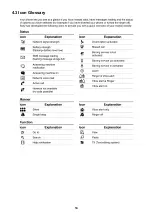
Page 14: ...14 4 3 Icon Glossary ...

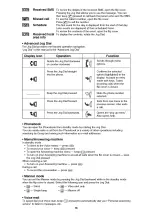
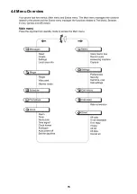
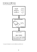
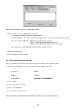
Page 15: ...15 4 4 Menu Overview ...
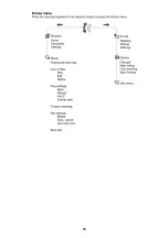
Page 16: ...16 ...

Page 17: ...ompartment should not be removed at all The IMEI number is the electronic identification of the hardware and it is stored electronically There should be no discrepancy between the number on the sticker and the number within the set logic allowed Follow the disassembly procedure in the numerical order given CABINET FRONT SUB ASSY LCD ...

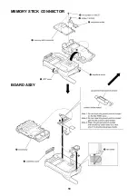
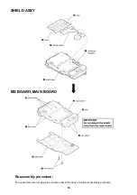
Page 18: ...18 MEMORY STICK CONNECTOR BOARD ASSY ...

Page 19: ...19 SHIELD ASSY MS BOARD MAIN BOARD Re assembly procedure To re assemble the unit apply the reverse order of the above mention disassembly procedure ...

Page 20: ...his unit acts as a base station providing all the necessary GSM signalling requirements and provides GSM signal measuring facilities as well CMD MZ5 Battery Pack Test SIM Card RF input Connector STC 02 Part No 1 792 726 11 RF output SMA plug Use special RF Adapter for connection of STC 02 to your GSM Tester ...

Page 21: ... For Connection To GSM Measure Equipment Level Test Procedure with GSM TESTER recommendation Simulate GSM call processing to check the functionality of transmitting and receive audio signals of loudspeaker and microphone Basic GSM transmission reception parameter testing to ensure that handset s performance compiles with standard GSM specification DATA TRANSFER JIG HOOK RELEASE JIG SERVICE TEST CO...

Page 22: ...nnector Attach battery pack to CMD MZ5 the CMD MZ5 is powered up from the battery pack The initial settings of the flash exe program may not correspond with the normally correct settings It is highly advisable to check the settings first see 6 3 Software set up 6 3 Software set up 6 3 1 Download Software to Mobile Software Update Start the program flash exe by double clicking on its icon in the Wi...

Page 23: ...n software do not use modify Flash erase area is automatically calculated with the contents of the life Switch on the CMD MZ5 Now the program run automatically 6 3 2 Save Personal Data in Mobile The set up and all requirements for this data transfer are the same as for the software update Check if the settings for the Com Port Speed and Load Option are correct Com Port COM 1 Speed 115200 Load Opti...

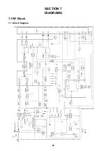
Page 24: ...24 SECTION 7 DIAGRAMS 7 1 RF Block 7 1 1 Block Diagram ...

Page 25: ...cy 880MHz by two at the signal reception from VCO602 and they become base band IQ signals in the IC604 The received signals that became base band IQ signals pass through low pass filter in the IC604 to remove unnecessary signals and then they are sent to the base band side The signals sent to the base band side are IQ signals having 1 4V DC offset 2 Transmitter Section IQ signals transmitted from ...

Page 26: ...d Reception 1365 2 1439 8MHz 200kHz step The output of VCO601 is entered to the FL601 and distributed to two outputs One of these outputs returns to the IC601 and another output is entered to the IC604 In the transmission of GSM band the signal entered to the IC604 is divided into two internally and therefore the frequencies of every 400kHz step are used in this case only The VCO602 is for local P...

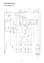
Page 27: ...27 7 2 Base Band Block 7 2 1 Block Diagram 1 2 ...

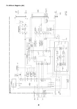
Page 28: ...28 7 2 2 Block Diagram 2 2 ...

Page 29: ...stored 4 IC104 This device provides the functions such as key scanning interrupt extension power supply circuit control watch dog timer voltage monitoring and output port extension It is connected to the system controller IC101 data bus 5 IC203 This device provides the audio signal recording and playing function and also the audio path switching function It is capable of recording for 4 minutes at...

Page 30: ...30 7 3 Memory Stick Block 7 3 1 Block Diagram 1 2 ...

Page 31: ...31 7 3 2 Block Diagram 2 2 ...

Page 32: ...ry stick Also at the playing the encrypted data in the memory stick are decrypted and led to the digital signal processing IC IC301 4 Audio Path Control Section The output paths of received audio played back audio terminating tone and key tone are switched over to the receiver headphone or earphone and audio signals are mixed and the volume is controlled then the signals are led to the headphone a...

Page 33: ...5 1 7 5217 68 66 86 21 9 5 02725 66 5 1 9 5 02725 66 5 5 1 63 5 63 5 1 86 21 63 5 6 7 58 5 2 5 53 21 7 8 66 8 06 29 5 53 21 86 21 5 1 5 02817 66 29 5 06 6 5 35 6 21 87721 06 7 211 725 0 025 67 17 17 11 1 7 5 5 66 1 211 725 6 0 6 5 527 5 6 7 1 211 725 2 5 72 2 5 77 5 3 211 725 29 5 211 725 Note The parts with no reference in the exploded view are not supplied ...

Page 34: ...21 25 211 7 21 237 32 5 6833 25 6 7 8 32 5 6833 25 6 7 8 55 77 5 3 0 025 67 25 211 7 21 1 2 0 18 16758 7 21 1 6 0 18 16758 7 21 50 1 0 18 16758 7 21 5 1 0 18 16758 7 21 7 1 0 18 16758 7 21 87 5 1 0 18 16758 7 21 63 1 6 32578 8 6 110 Analog Audio recording cable 1 Optical Audio recording cable 1 ...

Page 35: ...Sony Corporation Digital Telecommunication Company 9 870 403 01 2001 5 Published by After Sales Service ...

Reviews: