DSC-F717
COVER
COVER
4-2. SCHEMATIC DIAGRAMS
4-3. PRINTED WIRING BOARDS
4-2. SCHEMATIC DIAGRAMS
4-3. PRINTED WIRING BOARDS
MOUNTED PARTS LOCATION
MOUNTED PARTS LOCATION
4-49
4-50
For Printed Wiring Board.
•
:Uses unleaded solder.
• There are a few cases that the part isn't mounted in this
model is printed on this diagram.
• See page 4-79 for printed parts location.
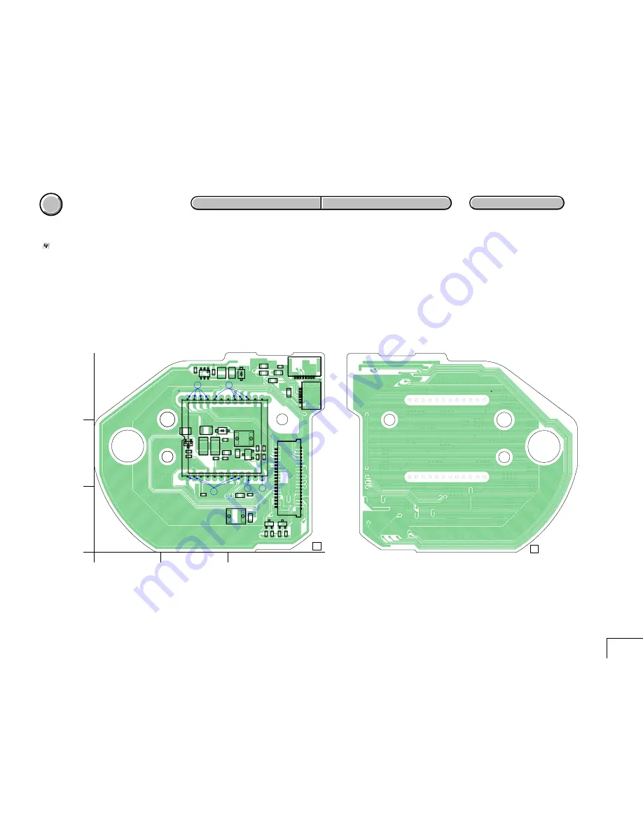
CD-408
CD-408 (CCD IMAGER)
Q301
E
C
B
Q302
Q303
L301
L302
FB301
FB302
FB303
FB304
FB305
R306
R307
R308
R309
R310
R311
R312
R313
R314
R315
R316
R317
R318
R319
CN301
1
2
38
39
CN302
1
6
CN303
1
8
R320
C301
C302
C303
B
+
C304
B
+
C305
TH301
C306
C307
C308
C309
C310
C311
C312
D301
D302
D303
D304
IC301
C
E
B
A
K
K
A
K
K
1-686-185-
11
CD-408 BOARD (SIDE A)
A
B
C
1
05
2
3
1
12
13
24
1
2
4
5
3
CD-408 BOARD (SIDE B)
1-686-185-
11
05
Summary of Contents for CYBER-SHOT DSC-F717
Page 30: ...Schematic diagrams of the SY 080 board are not shown Pages from 4 9 to 4 22 are not shown ...
Page 46: ...Printed wiring boards of the SY 080 board are not shown Pages from 4 51 to 4 54 are not shown ...
Page 57: ...Waveforms of the SY 080 board are not shown Pages 4 74 and 4 75 are not shown ...
Page 62: ...Mounted parts location of the SY 080 board are not shown Pages 4 80 is not shown ...
Page 79: ...DSC F717 118 Sony EMCS Co 2002I0500 1 2002 9 Published by DI Customer Center 9 929 994 31 ...


