2-7
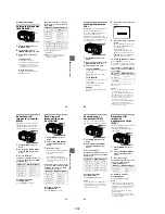
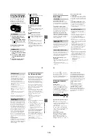
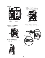
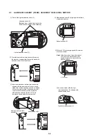
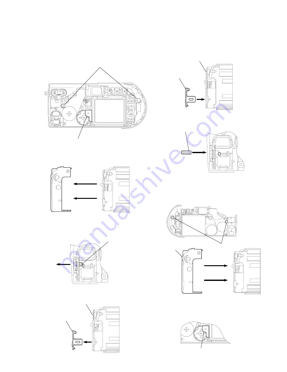
2-8. INNER CABINET (REAR) ASSEMBLY REPLACING METHOD
Parallel pin (dia. 1.6
×
5)
3
Pull off the forcibly fitted parallel pin (dia. 1.6
×
5)
in the direction of arrow
A
.
A
Adhesive sheet (A)
[Between inner cabinet (rear) assembly
and aluminum cabinet (rear) assembly]
Light interception sheet (F)
1
Peel off the light interception sheet (F).
2
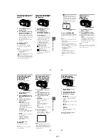
From the aluminum cabinet (rear) assembly, remove
the inner cabinet (rear) assembly stuck with
adhesive sheet (A) at two places.
Inner cabinet (rear) assembly
4
Pull the jack cover off the inner cabinet (rear).
Jack cover
Inner cabinet (rear) assembly
5
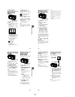
Insert the jack cover into new inner
cabinet (rear) assembly.
Jack cover
Parallel pin (dia. 1.6
×
5)
6
Forcibly fit the Parallel pin (dia. 1.6
×
5).
Aluminum cabinet (rear)
assembly
adhesive sheet (A)
7
Check if adhesive sheet (A) remains on the aluminum
cabinet side, and if so, remove it. Peel stripping sheet off
the adhesive sheet (A) at two places in the inner cabinet (rear)
assembly. Insert the inner cabinet (rear) assembly,
aligning with the aluminum cabinet.
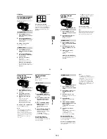
Light interception sheet (F)
8
As shown below, affix the light
interception sheet (F), aligning with
the positioning boss.

