DSC-P9
5-29
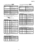
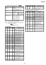
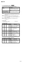
19. CCD Black Defect Compensation
RadarW
RadarW
RadarW
RadarW
RadarW
Mode
CAMERA
Subject
Clear chart
(Standard picture frame with the
zoom lens at WIDE end)
Measurement Point
Displayed data of page: 6,
address: 55
Measuring Instrument
Adjusting remote commander
Note 1:
Check that the data of page: 6, address: 02 is “00”.
If not, turn the power of unit OFF/ON.
Note 2:
Check that there are no dust, no dirt and reflection of the
clear chart.
Note 3:
Any subject other than the clear chart should be in the
screen.
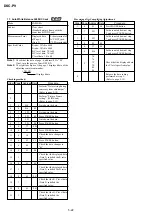
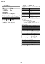
Adjusting method:
Order Page Address Data
Procedure
1
Perform “Data setting during
camera system adjustment”.
(Refer to page 5-14)
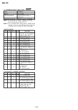
2
E
65
Note down the data.
3
E
65
4C
Press PAUSE button.
4
6
2C
01
5
6
90
00
6
6
91
03
7
6
92
00
8
6
93
00
9
6
01
79
Press PAUSE button.
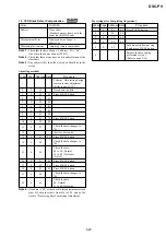
10
6
30
08
11
6
07
Check the data changes to
“01”.
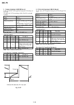
12
Wait for 4 seconds.
13
6
01
8D
Press PAUSE button.
14
6
02
Check the data changes to
“01”.
15
6
55
Check the data.
00 to 14 : Normal
15 to FF : Defective
(Note 4)
16
6
01
00
Press PAUSE button.
17
E
65
5A
Press PAUSE button.
18
6
01
89
Press PAUSE button.
19
6
02
Check the data changes to
“01”.
20
6
55
Check the data.
00: Normal
01 to FF: Defective
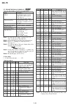
Note 4:
If the data is “00” at the check in this adjustment method
order #15, skip the orders from #16 to #20 , and go for-
ward to “Processing after Completing Adjustment.
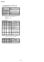
Processing after Completing Adjustment:
Order Page Address Data
Procedure
1
6
01
00
Press PAUSE button.
2
6
2C
00
3
6
30
00
4
6
91
00
5
E
65
Set data noted down at step
2, and press PAUSE button.
6
Release the data setting
performed at step 1.
(Refer to page 5-14)


