DSC-P9
5-32
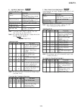
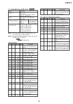
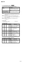
21. AF Illumination Check
RadarW
RadarW
RadarW
RadarW
RadarW
Check the deviation of optical axis of AF illuminator.
Mode
CAMERA
Subject
Flash adjustment box (Note 3)
(50 cm or 1 m from the front of
lens)
Measurement Point
Check operation on monitor TV
Measuring Instrument
Note 1:
Perform checking by making the shooting surface of the
Flash adjustment box perpendicular to the optical axis of
the camera.
Note 2:
Perform this checking in the Flash adjustment box.
Restrict external light to enter the Flash adjustment box
as less as possible.
Note 3:
Refer to “4. Preparing the Flash adjustment box”.
(See page 5-7)
Switch setting
1) FOCUS (Menu setting) .............................. MULTI AF
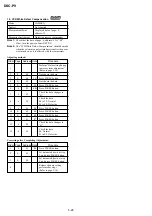
Adjusting method:
Order Page Address Data
Procedure
1
Perform “Data setting during
camera system adjustment”.
(Refer to page 5-14)
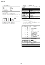
2
9
A9
Set the following data, and
press PAUSE button.
06: 50 cm
04: 1 m
3
6
01
EF
Press PAUSE button.
4
6
02
Check the data changes to
“01”.
5
F
10
Check the data.
00: Normal
01 to FF: Defective
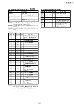
Processing after Completing Adjustment:
Order Page Address Data
Procedure
1
6
01
00
Press PAUSE button.
2
Release the data setting
performed at step 1.
(Refer to page 5-14)


