background image

DSC-QX10

4-3

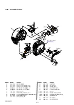
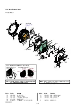
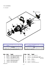
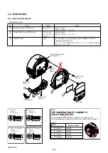
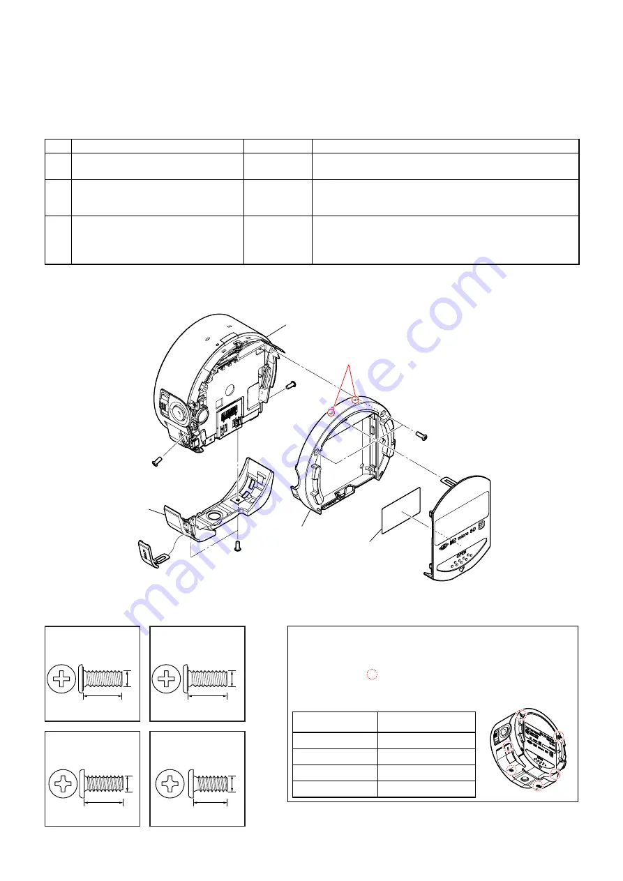
4-3. MAIN BLOCK

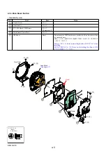
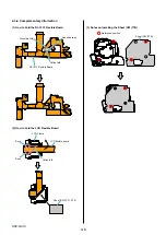
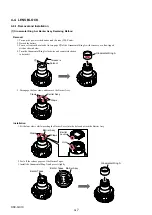
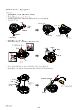
4-3-1. Rear Cabinet Section

• Disassembly order

No.

Part

Item

Note

1

Bottom Cabinet, USB Lid Assy

#2 or #10 x 2

Refer to Note 1.

Note 1を参照してください。

2

Cabinet (Rear) Assy, BT Lid Assy

#2 or #10 x 2
#11 or #23 x 2
Claw x 2

Refer to Note 1.

Note 1を参照してください。

3

ID-PASS label

Seal

ID-PASS label is not supplied, but this is included in SY-1024 
Complete Board (Service).

ID-パスラベルは供給されませんが,サービス用SY-1024基
板に含まれています。

(Claws)

1

2

3

#2/#10 

(

1

)

(Note 1)

USB Lid Assy

BT Lid Assy

#11/#23 

(

2

)

(Note 1)

#2/#10

(

2

)

(Note 1)

#2/#10 

(

2

)

(Note 1)

Front Cabinet Section

(See page 4-4)

#2: M1.7 X 4.0

(Black)
2-635-562-31

4.0

1.7

#10: M1.7 X 4.0

(Silver)
2-599-475-31

4.0

1.7

#11: M1.7 X 4.0 (Tapping)

(Silver)
3-078-890-11

4.0

1.7

#23: M1.7 X 4.0 (Tapping)

(Black)
3-080-204-11

4.0

1.7

Screw's
Ref. No. (Parts Color)

Cabinet's Color

Table 2-1

Note 1 

THE COMBINATION OF CABINET’S

COLOR AND SCREW

#2 (Black)

#10 (Silver)

#11 (Silver)

#23 (Black)

BLACK

WHITE

WHITE

The screw pointed       is different according to the cabinet's color.
For the combination of cabinet's color and screw, please refer to Table 2-1.

BLACK

Summary of Contents for Cyber-shot DSC-QX10

Page 1: ...se Model Tourist Model Photo Black 9 834 748 11 DSC QX10 2013H08 1 2013 08 Note Be sure to keep your PC used for service and checking of this unit always updated with the latest version of your anti virus software In case a virus affected unit was found during service contact your Service Headquarters 注意 修理時に使用するパソコンは ウィルス検出ソフトが常にアップ デートを行っているパソコンを使用してください もし 修理を 行うセット もしくはパソコンがウィルスに感染している事が判 明した場...

Page 2: ...ted pattern copper foil may peel away if the heated tip is applied for too long so be careful Unleaded solder is more viscous sticky less prone to flow than ordinary solder so use caution not to let solder bridges occur such as on IC pins etc Be sure to control soldering iron tips used for unleaded solder and those for leaded solder so they are managed separately Mixing un leaded solder and leaded...

Page 3: ...検を サービスのために取外したネジ 部品 配線がもとどお りになっているか またサービスした個所の周辺を劣化 させてしまったところがないかなどを点検し 安全性が 確保されていることを確認して下さい 5 チップ部品交換時の注意 取外した部品は再使用しないで下さい タンタルコンデンサのマイナス側は熱に弱いため交換 時は注意して下さい 6 フレキシブルプリント基板の取扱いについて 半田こてのこて先温度は約350 に設定してくださ い 同一パターンに何度もコテ先を当てないで下さい 3 回以内 パターンに力が加わらないよう注意して下さい サービス 点検時には次のことにご注意ください 無鉛半田について 本機には無鉛半田が使用されています 無鉛半田を使用している基板には 無鉛 Lead Free を意味 するレッドフリーマークがプリントされています 注意 基板サイズによっては 無鉛半田を使用していても ...

Page 4: ...PA compliant including NP BN battery pack Memory Stick Micro media Approx 105 g 3 7 oz Power Rechargeable battery pack NP BN 3 6 V Power consumption during shooting 1 1 W 概略仕様 外形寸法 CIPA準拠 幅 高さ 奥行き 62 4 mm 61 8 mm 33 3 mm 本体質量 CIPA準拠 バッテリー NP BN メモリースティックマイクロ 含む 約105 g 電源 リチャージャブルバッテリーパックNP BN 3 6 V 消費電力 撮影時 約1 1 W ENGLISH JAPANESE ...

Page 5: ...er que par une pièce portant le numéro spécifié CAUTION Danger of explosion if battery is incorrectly replaced Replace only with the same or equivalent type Dispose of used batteries according to the instructions 注意 如果电池更换不当会有爆炸危险 只能用同样类型或等效类型的电池来更换 务必按照说明处置用完的电池 Color Indication of Appearance Parts Example SILVER Cabinet s Color Silver Parts Color JAPANESE 使用上の注意 ここに記載されている部品は 補修用部品であるため 回路図及びセット...

Page 6: ...ASSY 770 B USB BLACK 2 X 2588 185 1 LID ASSY 770 W USB WHITE 3 X 2588 071 1 LID ASSY 770 BT BLACK 3 X 2588 186 1 LID ASSY 770 W BT WHITE 4 X 2587 926 1 CABINET REAR ASSY 770 B BLACK 4 X 2588 184 1 CABINET REAR ASSY 770 W WHITE 2 2 635 562 31 SCREW M1 7 Note 1 10 2 599 475 31 SCREW M1 7 Note 1 11 3 078 890 11 SCREW TAPPING Note 1 23 3 080 204 11 SCREW TAPPING P2 Note 1 Screw s Ref No Parts Color Ca...

Page 7: ... RL 1019 FLEXIBLE BOARD COMPLETE SERVICE 57 4 472 483 01 MICROPHONE CUSHION 58 4 484 268 01 SHEET CM FPC 770 59 4 472 477 01 CLAMP LCD 60 4 472 481 01 CUSHION LCD 61 4 485 165 01 TAPE AS 0609 62 4 485 166 01 SHEET BT FPC 770 63 1 882 890 11 BT 066 FLEXIBLE BOARD ANT901 1 754 863 11 ANTENNA BT901 1 780 826 11 TERMINAL BOARD BATTERY LCD901 1 811 854 11 DISPLAY PANEL LIQUID CRYSTAL SP901 1 858 826 11...

Page 8: ... 4 473 721 01 FRAME 770 USB 106 A 1970 987 A SY 1024 BOARD COMPLETE SERVICE 107 4 472 499 01 SHEET CM 770 Note 2 108 4 484 268 01 SHEET CM FPC 770 109 4 484 269 01 SHEET BT 770 1 2 635 562 11 SCREW M1 7 A B A C B C 1 1 1 1 1 1 1 1 103 109 104 102 106 107 Note 2 108 105 ns ns ns ns Lens Section See page 1 5 Note 1 SY 1024 Note 1 NOTES ON HOLDING THE LENS BLOCK Hold the Lens Block at the center of b...

Page 9: ...TED ASSY 157 A 1861 309 A DC MOTOR WORM ASSY 158 X 2582 885 1 LF 139 FLEXIBLE BOARD COMPLETE 159 A 1913 151 A CD 841 FLEXIBLE BOARD COMPLETE Including CMOS imager 160 CAUTION TAPE FPC 161 4 294 347 01 RETAINER FG 176 3 947 504 31 SCREW M1 2 258 4 299 468 11 SCREW TAPPING UB1 2 CH ns ns ns 158 156 157 155 154 161 153 152 Note 1 159 including CMOS imager 160 Size 10 1mm X 5 4mm 151 258 258 258 176 C...

Page 10: ...DSC QX10 1 6 1 2 FUSE SY 1024 BOARD F051 Primary side F052 5 0V 3 0 4 2V Ref No Part No Description F051 1 576 415 31 FUSE 2A 32V F052 1 576 415 31 FUSE 2A 32V ...

Page 11: ...ide FRENCH SPANISH 904 4 474 751 31 Quick Start Guide SIMPLIFIED CHINESE 905 4 474 752 01 Reference Guide JAPANESE 905 4 474 752 11 Reference Guide ENGLISH FRENCH SPANISH 905 4 474 752 21 Reference Guide SIMPLIFIED CHINESE 906 4 480 203 11 Instruction Manual ENGLISH FRENCH SPANISH GERMAN ITALIAN DUTCH PORTUGUESE SWEDISH RUSSIAN KOREAN TRADITIONAL CHINESE ARABIC Ref No Part No Description 8 022 156...

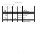
Page 12: ...ard Red Red Lit Recording a movie Green Receiving power Orange Charging Red flashing Lit Lit Memory card full capacity Red flashing Flashing 2Hz Memory card error Turn the power off and on again or taking out and inserting the memory card Green Red Flashing 1Hz Recovering Red flashing Flashing Battery error Turn the power off and on again Green flashing Flashing Empty Battery is empty Red flashing...

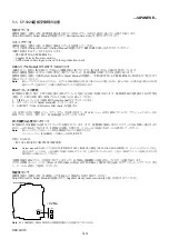
Page 13: ...aded Adjust manual 3 Execute Wireless LAN check on the ADJUST tab If Wireless LAN check is not executed and the backup data before replacement is restored the MAC address in the Wi Fi module does not match the MAC address in the flash memory causing an error during Wi Fi transfer Password required for Wi Fi connection A password required for Wi Fi connection is recorded in every SY board A label t...

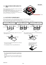
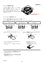
Page 14: ...d in completely Flexible Board Flexible Board Connector Connector Reference line Flexible Board Connector Connector Flexible Board Reference line Connector Connector Flexible Board Flexible Board Reference line Fig 1 Fig 2 Fig 3 When opening the connector s holder in direction A do not open it with excessive force When closing the connector s holder press it evenly while pushing a flexible board i...

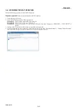
Page 15: ...de of the battery lid Procedure 2 Check the seal on the cover of the manual Procedure 3 Connect the unit and a PC with the micro USB cable then select Computer PMHOME WIFI_INF TXT of INFO 3 Confirm on the PC that the unit is detected as a connectable wireless network 4 To further confirm that the unit is connectable connect the unit to the PC and select Network and Internet Manage Wireless Network...

Page 16: ... 1 TISSホームページより最新版のAdjust manualをダウンロードする 2 ダウンロードしたAdjust manualをインストールする 3 ADJUSTタブにある Wireless LAN check を実施する これを実行せずに交換前のバックアップデータを書き戻すと Wi Fiモジュール内のMACアドレスとフラッシュメモリー内の MACアドレスが不一致となり Wi Fi転送時にエラーとなります Wi Fi接続に必要なパスワード SY基板にはWi Fi接続に必要なパスワードが記録されています また 補修用SY基板にはそのパスワードをお客様へ提示するた めのシールが貼られております SY基板を交換した場合は このシールを返却するセットに添付してください Note 新しいパスワードはセットとPCをUSB接続することで確認できます コンピュータ PMHOME INFO WIFI I...

Page 17: ... に押しながら 開閉部を均一に押してください 開閉部 コネクター フレキシブル基板 A A 開閉部 絶縁面 コネクター フレキシブル基板 B フラットケーブルおよびフレキシブル基板の端子面に欠け 折れ等がないことを確認してください 金メッキされているフレキシブル基板には 強い負担をかけ ないでください 先端の剥がれたメッキ部はカットして 除去してください メッキ破片がコネクター内に残って いる場合もあるので注意してください コネクターを取り外す際に 線材部 極細 を持って引っ張る と断線する恐れがありますので 絶対に線材部 極細 を持っ て引っ張らないでください 線材部 極細 を押さえながらコネクターを差し込むと 線材 部 極細 が断線する恐れがありますので 絶対に線材部 極細 には負担をかけないでください 3 2 レンズ交換時の注意 レンズ交換時 補修用レンズ添付データシートに掲載されて...

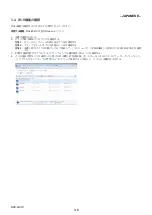
Page 18: ...2 以下の手順でSSIDとパスワードを確認する 方法1 セットのバッテリーふた裏にあるラベルを確認する 方法2 クイックスタートガイドの表紙のシールを確認する 方法3 本機とPCをマイクロUSBケーブルで接続して コンピュータ PMHOME INFO の WIFI INF TXT を確認 する 3 PC側で接続可能なワイヤレスネットワークとして本機が検出されることを確認する 4 さらに接続可能なことを確認したい場合には本機とPCを接続後 コントロールパネルの ネットワークとインターネット ワイヤレスネットワークの管理 からネットワーク接続リストを開くと リストに本機が表示される JAPANESE ...

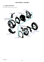
Page 19: ...embly in the numerical order given BT 066 Flexible Board RL 1019 Flexible Board 5 LCD Block 9 Main Frame q Front Plate 2 Rear Cabinet Block 4 Battery Clamp 6 Heat Sink 8 SY 1024 Board 7 Battery Terminal CD 841 Flexible Board qa Lens Block 3 Front Cabinet Block 1 Bottom Cabinet ...

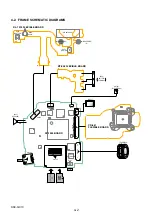
Page 20: ...ARD 1 10 BT901 BATTERY TERMINAL ANT901 Wi Fi ANTENNA SY 1024 BOARD CD 841 FLEXIBLE BOARD MULTI RESET LENS BLOCK SP901 SPEAKER NFC ANTENNA LCD901 18 1 CN704 S005 SHUTTER S006 ZOOM S001 POWER 1 51 1 38 2 39 1 5 1 8 1 9 1 2 0 2 1 50 51 10 1 12 11 CN405 CN701 8 10 9 1 CN702 CN703 RED BLK CN705 SE401 PITCH YAW S701 CN706 ...
Page 21: ...laws 1 2 3 2 10 1 Note 1 USB Lid Assy BT Lid Assy 11 23 2 Note 1 2 10 2 Note 1 2 10 2 Note 1 Front Cabinet Section See page 4 4 2 M1 7 X 4 0 Black 2 635 562 31 4 0 1 7 10 M1 7 X 4 0 Silver 2 599 475 31 4 0 1 7 11 M1 7 X 4 0 Tapping Silver 3 078 890 11 4 0 1 7 23 M1 7 X 4 0 Tapping Black 3 080 204 11 4 0 1 7 Screw s Ref No Parts Color Cabinet s Color Table 2 1 Note 1 THE COMBINATION OF CABINET S CO...

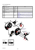
Page 22: ...How to Fold the RL 1019 Flexible Board when installing 取り付け時は 4 3 4 1 How to Fold the RL 1019 Flexible Board を参照してください 6 LCD Claw x 4 Refer to 4 3 4 2 How to Fold the LCD Flexible Board when installing 取り付け時は 4 3 4 2 How to Fold the LCD Flexible Board を参照してください 1 M1 7 X 2 5 Black 2 635 562 11 2 5 1 7 23 M1 7 X 4 0 Tapping Black 3 080 204 11 4 0 1 7 Claw Claw Claw Tape Solders Claws 5 4 6 1 3 2 Wi ...

Page 23: ... Do not reuse the CM Sheet because its adhesive force decreases when it is removed once CMシートは一度剥がすと粘着力が弱くなるため 再利用は しないでください Refer to 4 3 4 3 Notes on Installing the Sheet CM 770 when installing 取り付け時は 4 3 4 3 Notes on Installing the Sheet CM 770 を参照してください 1 M1 7 X 2 5 Black 2 635 562 11 2 5 1 7 A B A C B C Hook 1 3 USB Frame Front Plate 1 2 1 1 1 4 1 2 1 4 1 4 1 2 2 1 4 5 3 Lens Block See page 4 ...

Page 24: ...e RL 1019 Flexible Board Mountain fold Valley fold RL 1019 Flexible Board Adhesive tape 2 How to Fold the LCD Flexible Board Valley fold Sheet CM FPC 770 LCD flexible board LCD Clamp Boss Boss 3 Notes on Installing the Sheet CM 770 Sheet CM 770 Reference position ...

Page 25: ...s of the Barrier Tapes 3 Install the Ornamental Ring A and press it lightly 1 Turn on the power switch and extend the lens TELE end 2 Detach the battery 3 Pour a solvent such as alcohol to two gaps A of the Ornamental Ring A with tweezers or a fine tipped stick as shown below 4 Turn the Ornamental Ring A clockwise and counterclockwise to detach it Solvent A Tweezers Ornamental Ring A Barrier Assy ...

Page 26: ...Peel off the FPC Tape 6 Remove the LF 139 Flexible Board 7 Remove the four screws and remove the Z Retainer and the Sensor 8 Detach the Rear Mirror Plate and remove the Gear Worm Wheel Gear A and Gear B 9 Remove the two screws and remove solder at two locations to detach the DC Motor Worm Assy Gear A Gear B Gear Worm Wheel Ribs Rib Rib Rib Boss Boss Screws Screws Screw Sensor Boss Boss Flexible bo...

Page 27: ...Z Retainer Tighten the screws in the order of numbers in the figure below 6 Install the LF 139 Flexible Board 7 Connect the two Flexible Boards to the Connectors on the LF 139 Flexible Board 8 Stick the FPC Tape as shown in the figure below 9 Install the two Sensors and attach the FG Leaf Spring Note Attach the FG Leaf Spring in the correct orientation 10 Attach the FPC Retainer 1 2 3 4 Screws Scr...

Page 28: ...d 5 Peel off the FPC Tape Flexible board Flexible board FPC Tape Connector Connector Ribs Rib Rib Rib Boss Boss Boss Boss LF 139 Flexible Board Z Retainer Screws Screw Sensor 6 Remove the LF 139 Flexible Board 7 Remove the four screws and remove the Z Retainer and the Sensor Removal 1 Disengage the two claws and remove the FG Leaf Spring 2 Remove the two Sensors 3 Disengage the claw and remove the...

Page 29: ...A and Gear B 10 Turn portion A in the arrow direction to TELE end and remove the Flexible Board from the hole in the Stationary Tube Assy 9 Turn the Gear in the arrow direction to extend the Mirror Plate slightly 11 Turn portion A in the arrow direction to WIDE end and detach the Main Body from the Stationary Tube Assy 12 Remove the Main Body in the arrow direction 13 Remove the Rotary Cam Tube fr...

Page 30: ... Frame Assy Cam Tube A 3 Group Assy Tweezers Claw Claw 14 Turn the 3 Group Assy approx 20 in the arrow direction 15 Disengage the three claws with tweezers 16 Remove the Lens Block 17 Remove the 1 Frame Assy from the Cam Tube A ...

Page 31: ...Group Assy Straight Tube Block Straight Tube Straight Tube 18 Fully turn the Cam Tube B in the arrow direction 19 Remove the 2 Group Frame 20 Remove the Straight Tube Block 21 Turn the Straight Tube in the arrow direction to detach it from the Cam Tube B ...

Page 32: ...en install the Straight Tube to the Cam Tube B Note Be sure to set the Straight Tube at the correct insertion position 2 Turn the Straight Tube in the arrow direction to the maximum 3 Install the Straight Tube Block aligning the thinnest groove with the white part as shown in the figure and then turn the Cam Tube B in the arrow direction to the maximum 4 Install the 2 Group Frame at a position whe...

Page 33: ...tary Cam Tube with the semicircular cutout and the Gear edge set in the OK state shown in the figure 10 Install the Main Body so that the Flexible Board position matches the hole to pass the Flexible Board 5 Install the 1 Frame Assy so the Lever positions match Note Confirm that the Barrier closes when the 1 Frame Assy is pushed 6 Set the 3 Group Assy in the groove in the orientation where the Fle...

Page 34: ...in the arrow direction to extend the Mirror Plate slightly 12 Turn portion A in the arrow direction to TELE end and remove the Flexible Board from the hole in the Stationary Tube Assy 13 Install the Gear Worm Wheel Gear A and Gear B 14 Install the Rear Mirror Plate 15 Install four screws and the Z Retainer Tighten the screws in the order of numbers in the figure below 16 Install the LF 139 Flexibl...

Page 35: ...o Flexible Boards to the Connectors on the LF 139 Flexible Board 18 Stick the FPC Tape as shown in the figure below 19 Install the two Sensors and attach the FG Leaf Spring Note Attach the FG Leaf Spring in the correct orientation 20 Attach the FPC Retainer 21 Apply a voltage of 2 5 V to the DC Motor and retract the Lens 22 Perform the Flange Back Adjustment after the assembling DC2 5V ...

Page 36: ...he image through LCD or finder over full stroke between TELE end and WIDE end Barrier Check five postures horizontal upward downward upper lower oblique 45º The barrier must be opened and closed fully free from a sticking in the midway No abnormal sound must be heard during the operation Appearance condition Scratches or stains must not be noticeable except that the customer permits them Foreign m...

Page 37: ...he chart The mirror should not tilt on the chart 3 Set the camera to display the chart on LCD like in the following picture 4 Adjust the camera position to the center of the chart Adjust the tripod height and the position Lateral direction 5 Adjust the camera angle to the frame of the chart with tripod Remove the mirror 3 Shooting 1 Set Self Timer 2 Shot 4 Check the shot image 1 Check the shot ima...

Page 38: ...page 2 Double click Setup msi 3 The installation window appears Click Next Adjust manual installation starts 4 The widow to choose the destination folder of the Adjust manual program appears Click Next 5 When Adjust manual is installed normally the confirmation window appears Click Close The installer is closed JAPANESE これらの機種で調整を行なうには アジャストマニュアルとアジャストステーションが必要です アジャストマニュアルとアジャストステーションのインストール方法詳細は...

Page 39: ...Ver Date History Contents S M Rev issued 1 0 2013 08 Official Release Revision History ...

Reviews: