background image

4-4

DSC-S930

Ref. No.

Part No.

Description

Ref. No.

Part No.

Description

101

4-140-965-01 CCD PLATE SHEET

102

3-288-943-01 SCREW_TP_1.4_3_A_0.2_D=2.5

103

4-140-964-01 FILTER SET, LOWPASS

104

A-1709-331-A LENS BLOCK ASSY

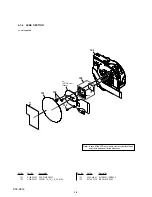
4-1-3. LENS  SECTION

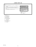
ns: not supplied

ns
(CCD Assy)
(Note)

ns

ns

ns

101

102

103

102

104

Note: In case of the CCD assy failure, contact your local Sony

service Headquarter for the measures.

Summary of Contents for Cyber-shot DSC-S930

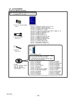
Page 1: ...el UK Model E Model Australian Model Chinese Model Korea Model Brazilian Model Tourist Model The components identified by mark 0 or dotted line with mark 0 are critical for safety Replace only with part num ber specified Les composants identifiés par une marque 0 sont critiques pour la sécurité Ne les remplacer que par une pièce portant le numéro spécifié Photo Silver DIGITAL STILL CAMERA DSC S930...

Page 2: ... 8 inches W approx 0 5 to 1 5 m 1 feet 7 3 4 inches to 4 feet 11 1 8 inches T Recording interval of Burst Approx 1 0 seconds Input and Output connectors USB communication Hi Speed USB USB 2 0 compliant LCD screen LCD panel 6 0 cm 2 4 type TFT drive Total number of dots 112 320 480 234 dots Power general Power LR6 size AA Alkaline batteries 2 3 V HR15 51 HR6 size AA Nickel Metal Hydride batteries 2...

Page 3: ...leasing the set to the customer ATTENTION AU COMPOSANT AYANT RAPPORT À LA SÉCURITÉ LES COMPOSANTS IDENTIFÉS PAR UNE MARQUE 0 SUR LES DIAGRAMMES SCHÉMATIQUES ET LA LISTE DES PIÈCES SONT CRITIQUES POUR LA SÉCURITÉ DE FONCTIONNEMENT NE REMPLACER CES COMPOSANTS QUE PAR DES PIÈSES SONY DONT LES NUMÉROS SONT DONNÉS DANS CE MANUEL OU DANS LES SUPPÉMENTS PUBLIÉS PAR SONY Unleaded solder Boards requiring u...

Page 4: ...ry pack with little remaining charge the battery pack may run out causing copying to fail or possibly corrupting the data You cannot select images to copy The original images in the internal memory are retained even after copying To delete the contents of the internal memory remove the Memory Stick Duo media after copying then format the internal memory Format in Internal Memory Tool A new folder ...

Page 5: ... UPPER ASSY 1 SCREW TP 1 4 2 5 2 SCREW_TP_1 4_3_A_0 2_D 2 5 3 LCD BRACKET 4 LCD 1 SCREW_TP_1 4_3 5_A0 3_D2 5_N 2 CABINET FRONT ASSY 3 BT LID 1 SCREW_TP_1 7_3 5_A0 5_D2 5 2 SCREW TP 1 7 3 3 CABINET REAR ASSY Note High voltage cautions Discharging the Capacitor Short circuit between two points with the short jig about 10 seconds R 1 kΩ 1 W Part code 1 215 869 11 Turn over the mylar ...

Page 6: ... SCREW_TP_1 4_3_A_0 2_D 2 5 4 CCD ASSY 5 LOW PASS FILTER SET 1 SCREW_TP_1 4_3 5_A0 3_D2 5_N 2 LENS BLOCK ASSY 3 MAIN FRAME SUB ASSY 1 SCREW_TP_1 4_3_A_0 2_D 2 5 2 ST BLOCK ASSY 1 SCREW_TP_1 4_3_A_0 2_D 2 5 2 SW BLOCK 1 SCREW_TP_1 4_3_A_0 2_D 2 5 2 MAIN BOARD HELP01 HELP02 HELP02 HELP01 1 ...

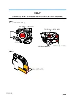
Page 7: ...ns and procedures of processing the flexible boards harnesses are shown HELP01 Be careful about the Lens Assy Be careful of the weld Keep clean these Pins Don t press the Barrier part Don t press the Sensor holder Don t press the AF motor HELP02 ...

Page 8: ...ER1 MD1 AUX_OUT USB_DET MIC_IN USB_D USB_D MD1 AUX_OUT MIC_IN USB_D USB_D MD1 MEMORY MEMORY MFD_CLE MFD 0 7 MFD_ALE MFD_RDY MFD_WP MFD_WE MFD_RE MFD_CE MFD_CLE MFD 0 7 MFD_ALE MFD_RDY MFD_WP MFD_WE MFD_RE MFD_CE 3 1VD 1 8VD DGND MS_CARD MS_CARD 3 1VD DGND POWER POWER 13V 4 3VD 7 5V 1 2VD 1 8VD 3 3V 3 1VD VP FLASH_VP CCD_ON DGND 3 3VS BAT_AD BAT_CHK 14V PWR_CTRL CCD_ON BAT_AD BAT_CHK PWR_CTRL 3 1V_...

Page 9: ...rts by reference number please include the board name The components identified by mark 0 or dotted line with mark 0 are critical for safety Replace only with part number specified Les composants identifiés par une marque 0 sont critiques pour la sécurité Ne les remplacer que par une pièce portant le numéro spécifié Color Indication of Appearance Parts Example SILVER Cabinet s Color Silver Parts C...

Page 10: ... TP 1 7 3 8 4 140 962 01 LCD BRACKET 4 1 1 OVERALL SECTION 4 1 EXPLODED VIEWS 9 A 1709 329 A SW BLOCK 10 4 145 605 01 SCREW_TP_1 7_3 5_A0 5_D2 5 11 X 2348 649 1 CABINET FRONT ASSY S SILVER 11 X 2348 650 1 CABINET FRONT ASSY B BLACK 11 X 2348 651 1 CABINET FRONT ASSY P PINK 12 4 140 969 01 BT LID S SILVER 12 4 140 970 01 BT LID B BLACK 12 4 140 971 01 BT LID P PINK 13 4 137 871 01 SCREW_TP_1 4_3 5_...

Page 11: ... 11 FUSE 1A 30V 4 1 2 MAIN FRAME SECTION ns not supplied ns Note 1 2 ns ns ns ns JC1 F2 F1 53 51 51 51 52 Lens Section See page 4 4 Note 1 In case of the main board failure contact your local Sony service Headquarter for the measures Note 2 The adjustment is not required after replacing these parts Refer to page 4 1 for mark 0 0F2 1 576 913 11 FUSE MICRO 1608 TYPE 1 6A 36V JC1 4 134 399 01 CONNECT...

Page 12: ...HEET 102 3 288 943 01 SCREW_TP_1 4_3_A_0 2_D 2 5 103 4 140 964 01 FILTER SET LOWPASS 104 A 1709 331 A LENS BLOCK ASSY 4 1 3 LENS SECTION ns not supplied ns CCD Assy Note ns ns ns 101 102 103 102 104 Note In case of the CCD assy failure contact your local Sony service Headquarter for the measures ...

Page 13: ...91 SIMPLIFIED CHINESE 4 126 518 11 RUSSIAN 4 126 518 21 ARABIC 4 126 518 31 PERSIAN 4 126 518 41 KOREAN 4 126 518 51 POLISH 4 126 518 61 CZECH 4 126 518 71 HUNGARIAN 4 126 518 81 SLOVAK 4 126 518 91 SWEDISH 4 126 519 11 FINNISH 4 126 519 21 NORWEGIAN 4 126 519 31 DANISH 4 126 519 41 THAI 4 126 519 51 MALAYSIAN 4 126 519 61 TURKISH 4 126 519 71 GREEK 4 126 519 81 UKRAINIAN Instruction Manual 4 126 ...

Page 14: ...DSC S930 Regarding Fuse MAIN BOARD Ref No F2 Part No 1 576 913 11 Description FUSE MICRO 1608 TYPE 1 6A 36V Ref No F1 Part No 1 576 363 11 Description FUSE MICRO 1005 TYPE 1A 30V ...

Page 15: ...Revision History Reverse DSC S930 Ver 1 0 Date 2009 02 History Official Release Contents S M Rev issued 985267411 pdf ...

Reviews: