– 40 –
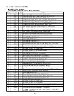
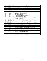
Pin No.
Pin Name
I/O
Function
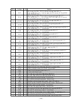
79
MUTE
I
Mute signal input terminal Fixed at “L” in this set
80
SENS
O
Internal status (SENSE) signal output to the system controller (IC701)
81
XRST
I
Reset signal input from the system controller (IC701) “L”: reset
For several hundreds msec. after the power supply rises, “L” is input, then it changes to “H”
82
DIRC
I
1-track jump mode input terminal Not used (fixed at “H”)
83
SCLK
I
Sense serial data reading clock signal input from the system controller (IC701)
84
DFSW
I
Defect on/off select signal input terminal Not used (fixed at “L”)
85
ATSK
I
Input terminal for the anti-shock Not used (fixed at “L”)
86
DATA
I
Serial data input from the system controller (IC701)
87
XLAT
I
Serial data latch pulse signal input from the system controller (IC701)
88
CLOK
I
Serial data transfer clock signal input from the system controller (IC701)
89
COUT
O
Track number count signal output terminal Not used (open)
90
DVDD
—
Power supply terminal (+3.3V) (digital system)
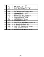
91
MIRR
O
Mirror detection signal output terminal Not used (open)
92
DFCT
O
Defect signal output terminal Not used (open)
93
FOK
O
Focus OK signal output terminal Not used (open)
94
FSW
O
Selection signal output terminal of the output filter for spindle motor Not used (open)
95
MON
O
Spindle motor on/off control signal output terminal Not used (open)
96
MDP
O
Spindle servo control signal output to the BA3890F (IC602)
97
MDS
O
Spindle servo control signal output to the BA3890F (IC602)
98
LOCK
O
GFS is sampled by 460 Hz “H” output when GFS is “H” Not used (open)
99
SSTP
I
Detection input from the sled limit-in detect switch (S910)
The optical pick-up is inner position when “H”
100
SFDR
O
Sled servo drive PWM signal (+) output to the MPC17A38ZVMEL (IC502)
Summary of Contents for D-V7000
Page 4: ... 4 SECTION 2 GENERAL This section is extracted from instruction manual ...
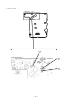
Page 10: ... 10 Connection Location CN501 CN701 MAIN Board Side A TP535 RFO TP534 VC TP524 TE ...
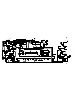
Page 12: ......
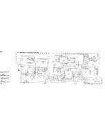
Page 13: ......
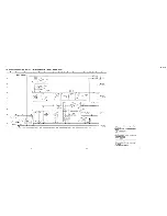
Page 14: ......
Page 15: ......

