19
D-VM1
Emergency Codes List
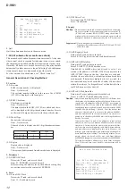
10: Communication to IC001 (RF-240 board) failed.
11: Each servo for focus, tracking, and spindle is unlocked.
12: Communication to EEPROM and IC1102 failed.
13: Writing of hours meter data to EEPROM and IC1102 failed.
14: Communication to Servo DSP and IC701 failed, or Servo DSP
is faulty.
20: Initialization of tilt servo and sled servo failed. They are not
placed in the initial position.
21: Tilt servo operation error
22: Syscon made a request to move the tilt servo to wrong posi-
tion.
23: Sled servo operation error
24: Syscon made a request to move the sled servo to wrong posi-
tion.
30: Tracking balance adjustment error
31: Tracking gain adjustment error
32: Focus balance adjustment error
33: Focus bias adjustment error
34: Focus gain adjustment error
35: Tilt servo adjustment error
36: RF equalizer adjustment error
37: RF group delay adjustment error
38: Jitter value after adaptive servo operation is too large.
40: Focus servo does not operate.
41: With a dual layer (DL) disc, focus jump failed.
50: CLV (spindle) servo does not operate.
51: Spindle does not stop.
60: With a DVD disc, Syscon made a request to seek nonexistent
address.
61: With a CD disc, Syscon made a request to seek nonexistent
address.
62: With a CD disc, Syscon made a request to seek nonexistent
track No.
63: With a DVD disc, seeking of target address failed.
64: With a CD disc, seeking of target address failed.
65: With a CD disc, seeking of target index failed.
70: With a DVD disc, physical information data could not be read.
71: With a CD disc, TOC data could not be read.
80: Disc type judgment failed.
81: As disc type judgment failed, retry was repeated.
82: As disc type judgment failed, a measurement error occurred.
83: Disc type could not be judged within the specified time.
84: Illegal command code was received from Syscon.
85: Illegal command was received from Syscon.
90: EEPROM checksum error
A0: Power was turned off due to temperature rise.
4-8. VERSION INFORMATION
On the Test Mode Menu screen, selecting 5 “R” displays the
ROM version and region code.
The parenthesized hexadecimal number in version field is
checksum value of ROM.
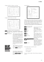
## Version Information ##
IF con.
Ver: x. xxx (xxxx)
Group 00
SYScon.
Ver: x. xxx (xxxx)
Model xx
Region 0x
Servo DSP Ver:1.XXX
Exit: RETURN
4-9. VIDEO LEVEL ADJUSTMENT
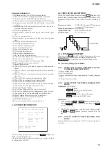
On the Test Mode Menu screen, selecting 6 “R” displays color
bars for video level adjustment. During display of color bars, OSD
disappears but the menu screen will be restored if pressing any
key.
Measurement point
: VIDEO OUT terminal (75
Ω
terminating
resistance)(AV output adapter)
Measuring instrument : Oscilloscope
Adjustment device
: RV901 on MAIN board
Specified value
: 1.0 ± 0.02 Vp-p
4-10. EVR/MON ADJUSTMENT
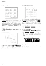
When you select 7 “R” on the Test Mode Menu screen, the screen
displays the 3.5/5-inch monitor adjustment menu. Press the
RETURN “R” key to return to the Test Mode Menu screen.
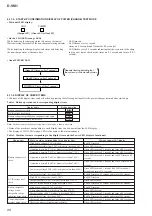
4-11. Power (Charge) Test Mode
4-11-1. ITEMS THAT CAN BE CONFIRMED BY THE
POWER (CHARGE) TEST MODE
• Battery voltage level
• DC IN voltage level
• Battery chargeable voltage or non-chargeable voltage judgment
status
• Charge end memory status
4-11-2. HOW TO START THE POWER (CHARGE) TEST
MODE
Conditions : DC IN status
Power off status
OPEN
B
knob is in the CLOSE status
(Close the disc lid.)
HOLD
.
switch is in the ON status
AVLS switch is in the LIMIT status
Operations :
1. While pressing the
u
and VOL+ buttons at the same time,
slide the OPEN
B
knob to open the lid, and change the AVLS
switch to NORMAL.
2. If the Test Mode starts once, you do not need to keep pressing
the
u
and VOL+ buttons. You may close the lid of the
disc.
4-11-3. HOW TO CANCEL POWER (CHARGE) TEST
MODE
Turning off the power (turning off the DC IN) cancels the power
test mode.
1.0
±
0.02 Vp-p


