6-6
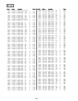
Memo Column
Initial Value
N
N
N
N
N
N
N
N
N
N
N
N
N
N
N
N
N
N
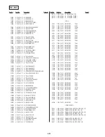
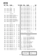
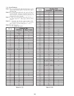
1-1-4. Page F Address
Note 1:
The
N
mark shown in the adjustment data memory column
indicates that the address data is fixed and is the same as
the initial value.
Note 2:
The initial adjustment data value is the value after “Page F
Data Initialization” and “Page F Data Modification” have
been executed. It is different from the value after all
adjustments have been executed.
Note 3:
( ) shows the value when the HI controller (IC2501, VC-
183 board) version is “1” (when page: 2, address: FF data
is “01”).
Note 4:
< > shows the value when the camera controller (IC205,
VC-183 board) version is other than “1” or “2” (when the
page: 6, address: FF data is other than “01” or “02” ).
Note 5:
CC: AEP, UK model
CF: US, Canadian and E model
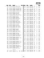
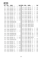
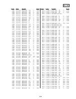
Address
Adjustment Data
Initial Value
Memo Column
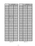
Address
Adjustment Data
Table 6-1-1 (1).
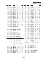
Table 6-1-1 (2).
10
11
12
13
14
15
16
17
18
19
1A
1B (Note 5)
1C
1D
1E
1F
20
21
22
23
24
25
26
27
28
29
2A
2B
2C
2D
2E
2F
30
31
00
00 or 04
1D
20 (NTSC), 30 (PAL)
00 (NTSC), 02 (PAL)
02
3B
00
7C
80
3F
CC or CF
30
2E
80
80
B4
55
86
7B
4A
15
90
19
82
13
00
00
40
1B
1B
AE
42
44
N
N
N
N
N
N
N
N
N
N
N
32
33
34
35
36
37
38
39
3A
3B
3C
3D
3E
3F
40
41
42
43
44
45
46
47
48
49
4A
4B
4C
4D
4E
4F
50
51
52
53
54
55
56
57
58
59
5A
5B
5C
5D
5E
5F
34
3C
89
59
38
41
20
00
19
00
1D
00
00
00
00
80
80
00
00
00
42
4D
44
4F
43
04
00
00
00
10
00 (NTSC), 04 (PAL)
39
8C
0C (NTSC), 0E (PAL)
41
16
77
50
75
83
26
75
A5
68
6C
00
Summary of Contents for DCR-PC7
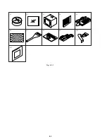
Page 41: ...6 2 Fig 6 1 1 J 1 J 2 J 3 J 4 J 5 J 6 J 7 J 8 J 9 J 10 J 11 ...
Page 92: ...6 57 ...
Page 95: ...6 60 ...
Page 96: ...6 61 ...
Page 97: ...6 62 ...
Page 104: ... 282 Sony EMCS Co DCR PC7 PC7E 9 973 919 11 2006I0500 1 2006 9 Published by Kohda TEC ...


