6-23
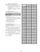
1-4. LCD SYSTEM ADJUSTMENTS
Note 1:
The back light (fluorescent tube) is driven by a high voltage
AC power supply. Therefore, do not touch the back light
holder to avoid electrical shock.
Note 2:
When replacing the LCD unit, be very careful to prevent
damages caused by static electricity.
Note 3:
Set the brightness to the center using the LCD BRIGHT
button (ME-4800 board).
[Power Supply Voltage]
Adjust the power supply voltage so that the voltage of Pin
9
(PANEL
UNREG) of CN5601 on PD-71 board becomes 8.4 ± 0.1 Vdc.
Mode
Signal
Adjustment Page
Adjustment Address
VTR stop
No signal
D
60, 61 C8 to D3, F0 to F7
Adjusting method:
1) Set data: 01 to page: 1, address: 00.
2) Select page: D, and input the data in the following table.
Note:
To write in the non-volatile memory (EEPROM), press
the PAUSE button of the adjusting remote commander
each time to set the data.
3) Set data: 00 to page: 1, address: 00.
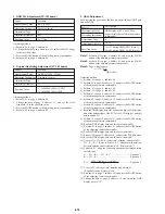
60
61
C8
C9
CA
CB
CC
CD
CE
CF
D0
D1
D2
D3
F0
F1
F2
F3
F4
F5
F6
F7
57
57
68
80
80
5A
3F
79
00
48
80
6D
FF
FF
3B
46
30 (NTSC), 2C (PAL)
DE (NTSC), DA (PAL)
82
40
A8 (NTSC), C8 (PAL)
4B
Data
Address
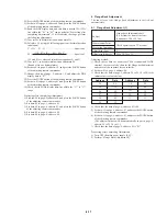
1. LCD Initial Data Input
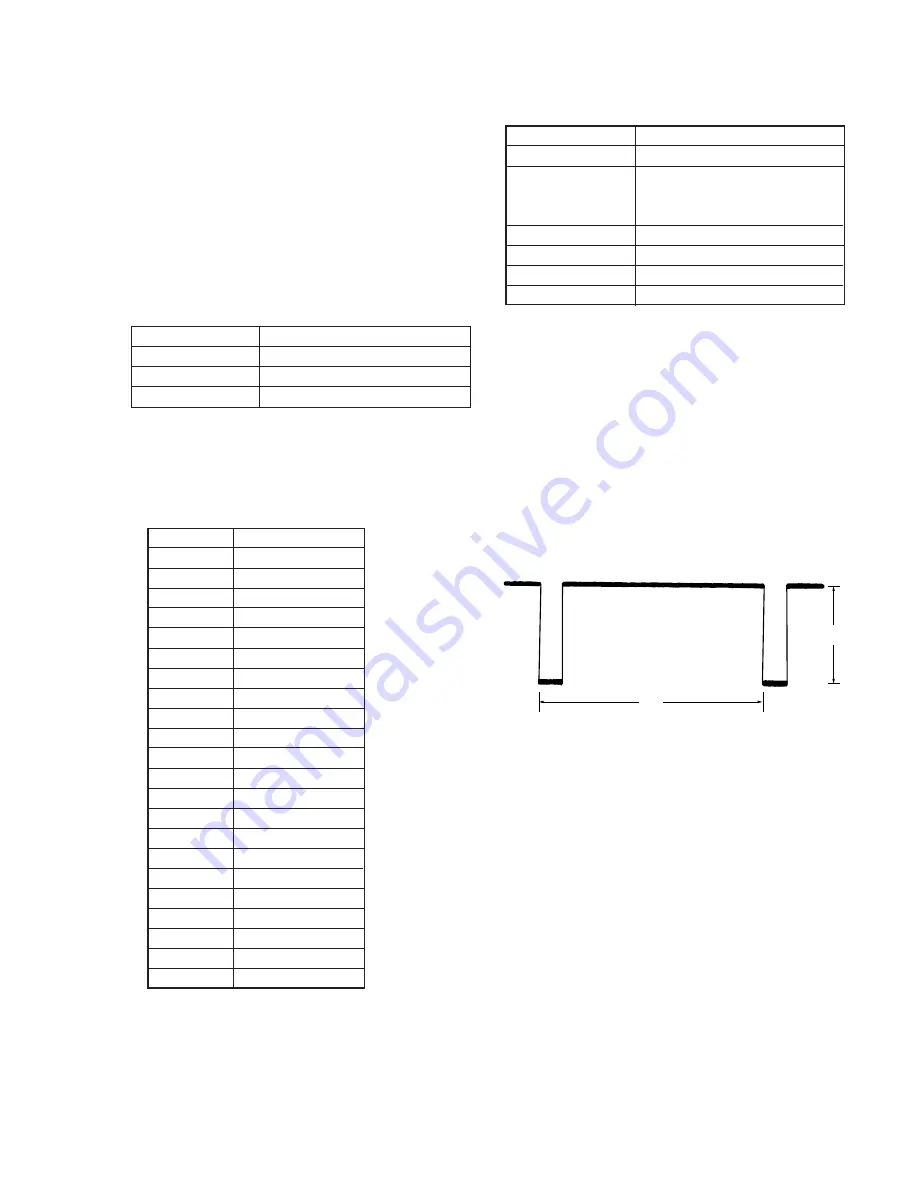
2. Input Signal Level Adjustment (VC-183 board)
Set the input signal level of LCD block and EVF block.
A
H
Fig. 6-1-15.
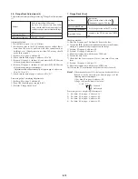
Mode
Signal
Measurement Point
Measuring Instrument
Adjustment Page
Adjustment Address
Specified Value
Pin
!§
of CN6202 (ADJ VG) or pin
2
of CN5600 (PANEL G) on PD-71
board
Oscilloscope
D
E6
A = 0.32 ± 0.05V
VTR playback
Optional recorded tape
Connection:
In case connect the oscilloscope to Pin
!§
of CN6202 (ADJ VG),
connect Pin
!§
of CN6202 and Pin
@¶
(or
@•
) of CN6200 (3.1V
power supply) with a 3.3 k
Ω
resistor.
3.3 k
Ω
resistor: 1-249-423-11
Adjusting method:
1) Set data: 01 to page: 1, address: 00.
2) Set data: 02 to page: 2, address: 49.
3) Set data: FF to page: 5, address: 00.
4) Change the data of page: D,address:E6, and set the VG signal
level (A) to the specified value.
5) Press the PAUSE button of the adjusting remote commander.
6) Set data: 00 to page: 2, address: 49.
7) Set data: 30 to page: 5, address: 00.
8) Set data: 00 to page: 1, address: 00.
Summary of Contents for DCR-PC7
Page 41: ...6 2 Fig 6 1 1 J 1 J 2 J 3 J 4 J 5 J 6 J 7 J 8 J 9 J 10 J 11 ...
Page 92: ...6 57 ...
Page 95: ...6 60 ...
Page 96: ...6 61 ...
Page 97: ...6 62 ...
Page 104: ... 282 Sony EMCS Co DCR PC7 PC7E 9 973 919 11 2006I0500 1 2006 9 Published by Kohda TEC ...

