6-24
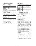
3. VCO Adjustment (PD-71 board)
Set the VCO freerun frequency.
If deviated, the LCD screen will be blur.
Mode
Signal
Measurement Point
Measuring Instrument
Adjustment Page
Adjustment Address
Specified Value
VTR Playback
Optional recorded tape
Pin
!™
of IC5801 (HSY) (CL5800)
Frequency counter
D
D1
f = 15734 ± 30 Hz (NTSC)
f = 15625 ± 30 Hz (PAL)
Adjusting method:
1) Set data: 01 to page: 1, address: 00.
2) Set data: 03 to page: 2, address: 49.
3) Change the data of page: D, address D1, and set the HSY signal
frequency (f) to the specified value.
4) Press the PAUSE button of the adjusting remote commander.
5) Set data: 00 to page: 2, address: 49.
6) Set data: 00 to page: 1, address: 00.
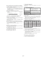
4. Horizontal Display Position Adjustment (PD-71 board)
Adjust the LCD horizontal position.
If deviated, the screen will deviate to the left or right.
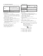
Fig. 6-1-16.
Mode
Signal
Measurement Point
Measuring Instrument
Adjustment Page
Adjustment Address
Specified Value
CH1: Pin
5
of CN5600 (XHD)
(CL5610)
CH2: Pin
!™
of IC5801 (HSY)
(CL5800)
Oscilloscope
D
D0
T = 2.25 ± 0.1 µsec. (NTSC)
T = 2.00 ± 0.1 µsec. (PAL)
VTR Playback
Optional recorded tape
Adjusting method:
1) Set data: 01 to page: 1, address: 00.
2) Change the data of page: D, address: D0, and set the time
difference (T) between the SYNC waveform and HSY waveform
to the specified value.
3) Press the PAUSE button of the adjusting remote commander.
4) Set data: 00 to page: 1, address: 00.
H
XHD
XSY
Enlargement
XHD
2.0V
HSY
2.0V
T
Summary of Contents for DCR-PC7
Page 41: ...6 2 Fig 6 1 1 J 1 J 2 J 3 J 4 J 5 J 6 J 7 J 8 J 9 J 10 J 11 ...
Page 92: ...6 57 ...
Page 95: ...6 60 ...
Page 96: ...6 61 ...
Page 97: ...6 62 ...
Page 104: ... 282 Sony EMCS Co DCR PC7 PC7E 9 973 919 11 2006I0500 1 2006 9 Published by Kohda TEC ...


