6-25
5. D Range Adjustment (PD-71 board)
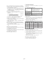
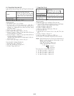
Set the D range of the LCD driver to the specified value. If dviated,
the LCD screen will become blackish or saturated (whitish)
Note:
Press the PAUSE button of the adjusting remote
commander each time to set the data.
3) Change the data of page: D, address: CC, and set the voltage (A)
between the pedestal and sync-tip to the specified value.
Note:
When select address: CC, select address: C8 first, and then
select address: CC.
4) Press the PAUSE button of the adjusting remote commander.
5) Input the following data to page: D, addresses: F2 and F3.
Note:
Press the PAUSE button of the adjusting remote
commander each time to set the data.
6) Set data: 00 to page: 1, address: 00.
1) Set data: 01 to page: 1, address: 00.
2) Input the following data to page: D, addresses: F2 and F3.
Mode
Signal
Measurement Point
Measuring Instrument
Adjustment Page
Adjustment Address
Specified Value
VTR playback
Audio operation check tape,
color bar portion
Pin
0
of CN5801 (VG) (CL5804)
Oscilloscope
D
CC
Address
Data
F2
F3
00
C0
Address
Data
F2
F3
30
DE
For NTSC model
For PAL model
Fig. 6-1-17.
A
2H
2H
A
A = 0.30 ± 0.05V
Summary of Contents for DCR-PC7
Page 41: ...6 2 Fig 6 1 1 J 1 J 2 J 3 J 4 J 5 J 6 J 7 J 8 J 9 J 10 J 11 ...
Page 92: ...6 57 ...
Page 95: ...6 60 ...
Page 96: ...6 61 ...
Page 97: ...6 62 ...
Page 104: ... 282 Sony EMCS Co DCR PC7 PC7E 9 973 919 11 2006I0500 1 2006 9 Published by Kohda TEC ...


