6-38
3-1-3. Adjusting Connectors
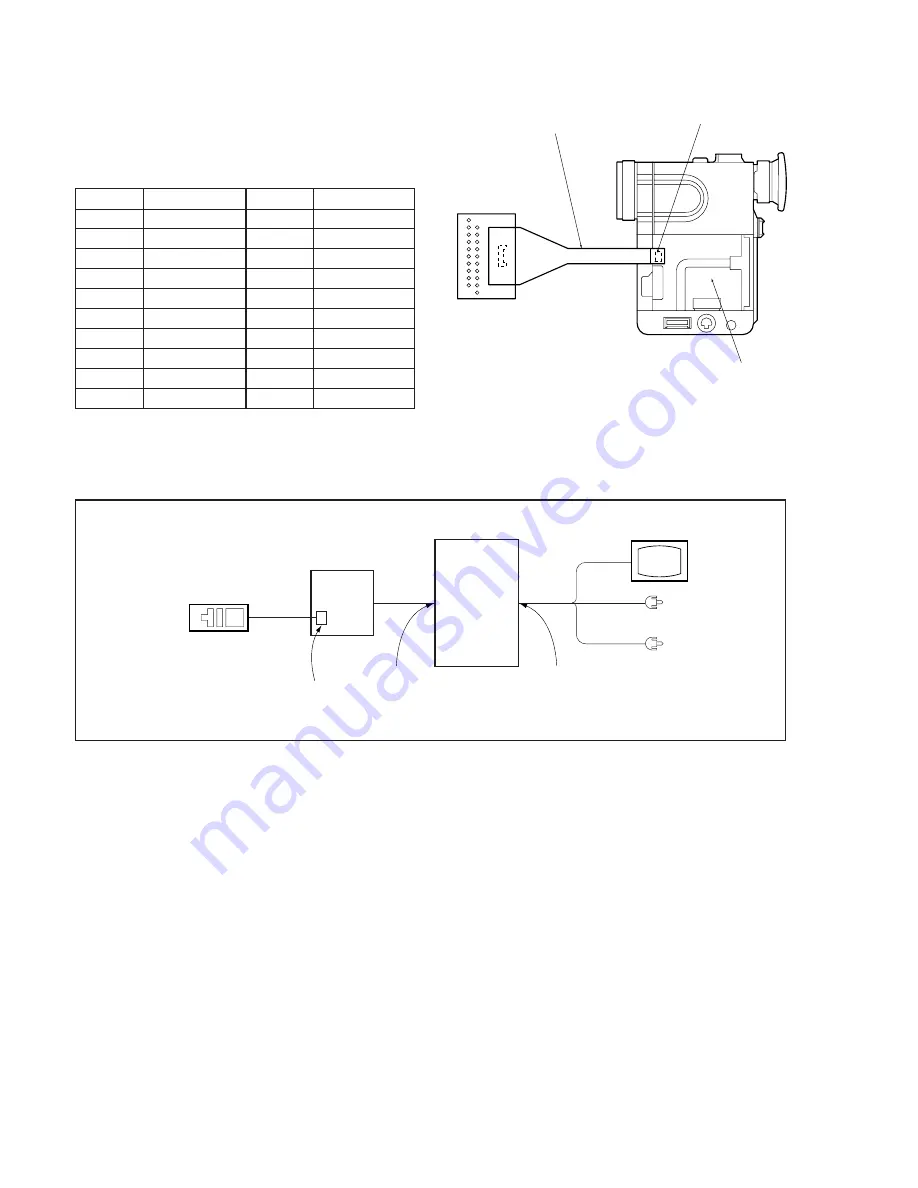
Some of the adjusting pints of the video section are concentrated at
CN6202 of the VC-183 board. Remove the battery plate and connect
the measuring instruments via the CPC-6 jig (J-6082-370-A) and
the CPC-6 terminal board jig (J-6082-371-A). The following table
lists the pin numbers and signal names of CN6202.
Table 6-3-1.
CPC-6 jig
CN6202
VC-183 board
CPC-6
terminal board jig
GND
ENV OUT
J SWP
EQ IN
AGC IN
GND
TRACK ID
FLTD
TMS
EVF VG
1
3
5
7
9
11
13
15
17
19
Pin No.
Signal Name
2
4
6
8
10
12
14
16
18
20
Pin No.
Signal Name
RF MONITOR
REF OUT
LOCK
VCC1
VCC2
C1ERP
TDOB
ADJ VG
TCK
TDI
Fig. 6-3-1.
3-1-4. Connection of Equipment
Connect the measuring instruments as shown in Fig. 6-3-2.
I/O board-1 jig
(J-6082-372-A)
Adjusting remote
commander
LANC terminal
26PIN
multi connector
Main unit
VIDEO
TV monitor
AUDIO L (White)
AUDIO R (Red)
Fig. 6-3-2.
VIDEO/AUDIO
HEADPHONE jack
Summary of Contents for DCR-PC7
Page 41: ...6 2 Fig 6 1 1 J 1 J 2 J 3 J 4 J 5 J 6 J 7 J 8 J 9 J 10 J 11 ...
Page 92: ...6 57 ...
Page 95: ...6 60 ...
Page 96: ...6 61 ...
Page 97: ...6 62 ...
Page 104: ... 282 Sony EMCS Co DCR PC7 PC7E 9 973 919 11 2006I0500 1 2006 9 Published by Kohda TEC ...


