DCR-TRV345E/TRV350/TRV351/TRV355E/TRV356E
COVER
COVER
3. BLOCK DIAGRAMS
3. BLOCK DIAGRAMS
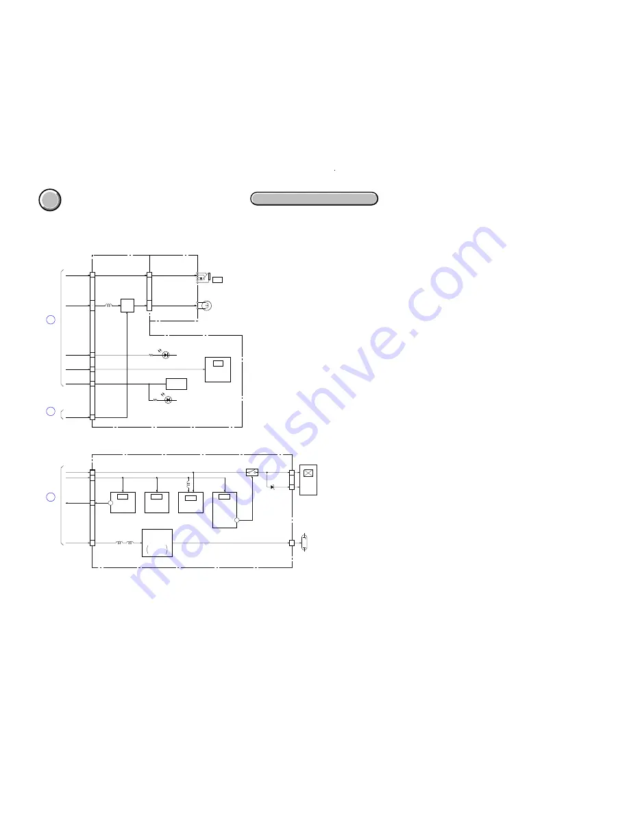
3-9. POWER BLOCK DIAGRAM (3/3)
3-17
3-18E
( ) : Number in parenthesis ( ) indicates the division number of schematic diagram where the component is located.
PD- 181 BOARD
PANEL 13.3V
PANEL 2.8V
BL CONT
BL REG
BL HIGH
CN5601
ND901
BACK
LIGHT
2.5INCH
COLOR
LCD UNIT
LCD901
CN5701
15
13
17
18
18
16
10
VDD
VDOG
TIMING
GENERATOR
IC5502
14
LCD DRIVER
IC5501
L5501
POFF
05
CN5501
Q5505, 5506
BACKLIGHT
DRIVE
CURRENT
DETECT
(2/2)
IC5602
SELECT
SWITCH
(2/2)
IC5601
T5601, Q5604
INVERTER
TRANSFORMER
L5602
L751
L5601
(1/2)
(1/2)
1
REMOTE
COMMANDER
RECEIVER
SE751, 752
CN754
Q751, 752
VL UNREG
V LIGHT PWM
VIDEO LIGHT
J002
PITCH, YAW
SENSOR
SI-036 BOARD
16
4
3
4
FP-575 FLEXIBLE
VIDEO
LIGHT
DRIVE
CN753
LIGHT VCC
9
10
11
24
D752, 753
(IR EMITTER)
D754
(TALLY)
IC751
LANC
A 4.6V
A 2.8V
MT 5V
1
10
LANC DC
LANC DC
POWER(1/3)
(PAGE 3-14)
A
POWER(1/3)
(PAGE 3-14)
C
POWER(2/3)
(PAGE 3-16)
D
Summary of Contents for DCR-TRV350 - Digital Handycam Camcorder
Page 52: ...Schematic diagrams of the VC 305 board are not shown Pages from 4 9 to 4 48 are not shown ...
Page 63: ...Printed wiring boards of the VC 305 board are not shown Pages from 4 67 to 4 70 are not shown ...
Page 70: ...Waveforms of the VC 305 board are not shown Pages from 4 82 to 4 87 are not shown ...
Page 73: ...Mounted parts location of the VC 305 board is not shown Pages from 4 90 to 4 91 are not shown ...


