background image

SDDS Player System

DIGITAL FILM SOUND READER

DFP-R3000

INSTALLATION MANUAL
1st Edition (Revised 1)
Serial No. 10001 and Higher

®

Summary of Contents for DFP-R3000

Page 1: ...SDDS Player System DIGITAL FILM SOUND READER DFP R3000 INSTALLATION MANUAL 1st Edition Revised 1 Serial No 10001 and Higher ...

Page 2: ...den die eine spezielle Befähigung dazu besitzen AVERTISSEMENT Ce manual est destiné uniquement aux personnes compétentes en charge de l entretien Afin de réduire les risques de décharge électrique d incendie ou de blessure n effectuer que les réparations indiquées dans le mode d emploi à moins d être qualifié pour en effectuer d autres Pour toute réparation faire appel à une personne compétente un...

Page 3: ...1 7 E 5 2 1 Installing to SIMPLEX 35 Strong International 1 8 E 5 2 2 Installing to SIMPLEX 70 1 13 E 5 2 3 Installing to CENTURY JJ Strong International 1 15 E 5 2 4 Installing to NORELCO AA II 35 70 Kinoton 1 17 E 5 2 5 Installing to V5 V8 V9 CINEMECCANICA 1 20 E 5 2 6 Installing to P35 Christie 1 23 E 5 3 Connecting to DFP D3000 1 26 E 5 4 Checking and Adjustment After Installation 1 27 E 5 4 1...

Page 4: ...his manual describes the information of the DFP R3000 and the information that premise the service based on parts DFP D3000 Maintenance Manual Prepared separately This manual describes the inspection of the DFP D3000 and the information that premise the service based on parts DFP D3000 R3000 Quick Start Guide Prepared separately This Quick Start Guide is intended to assist experienced cinema engin...

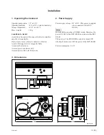
Page 5: ... 9 6 W 1 Operating Environment Operating temperature 5 dC to 40 dC Operating humidity 10 to 90 relative humidity Storage temperature _20 dC to 60 dC Mass weight 3 5 kg Locations to Avoid Areas where the unit will be exposed to direct sunlight or any other storong lights Dusty areas or areas where it is subject to vibration Areas with strong electric or magnetic fields Areas near heat sources Areas...

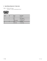
Page 6: ...ector SDDS I F DME 5W1S female Signal level SDI format digital audio signal Pin No I O Signal Description 1 I 24 V DC 24 V 2 NC No connection 3 GND Ground DC 24 V 4 CABLE SHIELD Ground Frame A1 O DATA SDDS data G1 DATA GND Ground Data 2 1 A1 3 4 G1 ...

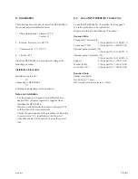
Page 7: ...ss 3 mm 5 Installation The following describes how to install the DFP R3000 to the various projectors indicated below 1 Strong International Simplex 35 70 Century JJ 2 Kinoton Noleroco AA II35 70 3 Cinemeccanica V9 V8 V5 4 Christie P35 Install the DFP R3000 to a projector according to the following procedure Installation Procedure Installation to projector Connecting to DFP D3000 Checking and adju...

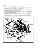
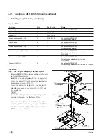
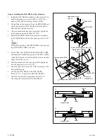
Page 8: ...and washer to take out the roller guide S3 assembly and roller guide shaft S3 35 6 Remove the one screw RK4 x 8 ornamental washer and washer to take out the roller guide T1 assembly 7 Remove the hexagon cap screw 4 x 10 washer W4 and spring washer SW4 from inside of the unit to take out the roller guide shaft T1 35 Front panel assembly Escutcheon Hexagon cap screw 4 x 10 Escutcheon Washer Ornament...

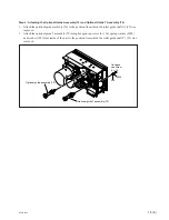
Page 9: ...position from which the roller guide shaft S3 35 was removed 2 Attach the optional guide T assembly 70 using hexagon cap screw 4 x 10 spring washer SW4 and washer W4 from inside of the unit to the position from which the roller guide shaft T1 35 was removed Hexagon cap screw 4 x 10 Optional guide T assembly 70 Optional guide assembly 70 SW4 W4 ...

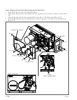
Page 10: ...Attach the front panel 70 R to the unit using the three screws B3 x 4 g and two screws B2 6 x 4 h 4 Attach the right side panel removed at the procedure 1 of Step 1 using the two screws B3 x 4 a and four screws B2 6 x 6 b Front panel 70 assembly Front panel 70 R Supports Supports Places for installing support B3 x 4 e B3 x 4 e B3 x 4 e B3 x 4 g B2 6 x 4 h B2 6 x 4 f B2 6 x 6 b B3 x 4 a Right side ...

Page 11: ... of the projector However the film speed must be stable within 5 when the first image frame passes by the reader of the DFP R3000 The tension of the film that is supplied to the DFP R3000 during film running is set to 0 5 to 59 N 50 to 600 fg Adjust so that the tension is within the above range between the beginning and end of the supplied film Required Tools Path adjustment tool Sony part No J 65...

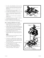
Page 12: ...djustment tool and DFP R3000 Procedure Step 1 Installing the Adapter A to the Projector 1 Remove REEL ARM or platter guide roller of supply reel side of the projector 2 Install the two optional guides E to the adapter C 3 Attach the adapter C to the projector using the two hexagon cap screws 3 8 16 1 4 Attach the adapter A tentatively to the adapter C using the two hexagon cap screws 3 8 16 2 and ...

Page 13: ...e film from the path adjustment tool 11 Remove the path adjustment tool from the adapter A Step 2 Installing the DFP R3000 to the Projector 1 Install the DFP R3000 tentatively in the adapter A with four hexagon cap screws M4 x 12 4 four washers W4 and four spring washers SW4 2 Put the film on the projector from the DFP R3000 and adjust the position arrow direction A of DFP R3000 so that the film i...

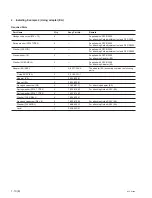
Page 14: ...d with DFP R3000 For attaching Adapter EA Washer W10 SMALL 2 Supplied with DFP R3000 For attaching Adapter EA Adapter EA ASSY 1 A 8327 348 A The adapter EA assembly contains the following parts Guide ASSY EA 2 X 3168 321 1 Adapter EA 1 3 204 905 01 Spacer EA 2 3 204 903 01 Hexagon cap screw 3 8 2 3 185 981 11 For attaching adapter EA Spring washer SW4 TYPE2 2 7 623 210 22 For attaching Guide ASSY ...

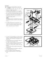
Page 15: ...rojector and adjust the attaching position of the path adjustment tool so that the film is smoothly fed onto the projector 6 After the adjustment has been completed tighten the two hexagon cap screws M4 x 12 3 7 Put a film on the path adjustment tool roller from the projector and adjust the attaching position of the adapter EA so that the film is smoothly fed onto the projector Especially adjust s...

Page 16: ...e REEL ARM to be used 5 Set the film to the DFP R3000 from the REEL ARM and adjust the installation position of the REEL ARM so that the film runs smoothly and the tension on both edges of the film is even 6 After the adjustment has been completed tighten the two hexagon cap screws 3 8 6 7 Paste the label as shown as A or B according to the film path direction 8 Connect the DFP R3000 to the DFP D3...

Page 17: ...dapter C 3 Attach the adapter C tentatively to the projector using the two hexagon cap screws 3 8 16 1 4 Put a film on the optional guide 70 mm from the projector and adjust the attaching position of the adapter C so that the film is smoothly fed onto the projector Especially adjust so that the tension on both edges of the film is even 5 After the adjustment has been completed tighten the two hexa...

Page 18: ...r washers W4 and four spring washers SW4 2 Put the film on the projector from the DFP R3000 and adjust the position arrow direction A of DFP R3000 so that the film is smoothly fed onto the projector 3 After the adjustment has been completed tighten the four hexagon cap screws M4 x 12 4 4 Reattach the REEL ARM of the projector tentatively to the DFP R3000 with two hexagon cap screws 3 8 16 5 n Fixi...

Page 19: ...ath adjustment tool and DFP R3000 Procedure Step 1 Installing the Adapter A to the Projector 1 Remove REEL ARM or platter guide roller of supply reel side of the projector 2 Attach the adapter A tentatively to the projector using the two hexagon cap screws 3 8 16 1 and wave washers n Fixing hole of adapter A varies depending on the projector to be used See the figure below 3 Attach the path adjust...

Page 20: ...Remove the path adjustment tool from the adapter A Step 2 Installing the DFP R3000 to the Projector 1 Install the DFP R3000 tentatively in the adapter A with four hexagon cap screws M4 x 12 4 four washers W4 and four spring washers SW4 2 Put the film on the projector from the DFP R3000 and adjust the position arrow direction A of DFP R3000 so that the film is smoothly fed onto the projector 3 Afte...

Page 21: ...hing adapter A Washer W8 3 7 688 000 31 For attaching adapter A Spacer EA 3 3 204 903 01 Adapter B 1 3 200 393 01 Screw PSW4 x 12 2 3 629 717 01 For attaching Adapter B Hexagon cap screw M4 x 12 4 Supplied with DFP R3000 For attaching Path adjustment tool and DFP 3000 Spring washer SW4 TYPE2 4 Supplied with DFP R3000 For attaching Path adjustment tool and DFP R3000 Washer W4 MID 4 Supplied with DF...

Page 22: ... the attaching position of the path adjustment tool so that the film is smoothly fed onto the projector 5 After the adjustment has been completed tighten the two hexagon cap screws M4 x 12 2 6 Put a film on the path adjustment tool roller from the projector and adjust the attaching position of the adapter A so that the film is smoothly fed onto the projector Especially adjust so that the tension o...

Page 23: ... hexagon cap screws 5 16 5 n Fixing hole position of the DFP R3000 varies depend ing on the REEL ARM to be used 6 Set the film to the DFP R3000 from the REEL ARM and adjust the installation position of the REEL ARM so that the film runs smoothly and the tension on both edges of the film is even 7 After the adjustment has been completed tighten the three hexagon cap screws 5 16 5 8 Connect the DFP ...

Page 24: ...ied with DFP R3000 For attaching Path adjustment tool and DFP R3000 Hexagon cap screw M8 x 35 4 7 683 476 04 For attaching adapter EA Adapter EA ASSY 1 A 8327 348 A The adapter EA assembly contains the following parts Guide ASSY EA 2 X 3168 321 1 Adapter EA 1 3 204 905 01 Spacer EA 4 3 204 903 01 Spring washer SW4 TYPE2 2 7 623 210 22 For attaching Guide ASSY EA Washer W4 MIDDL 2 7 688 004 12 For ...

Page 25: ... projector and adjust the attaching position of the path adjustment tool so that the film is smoothly fed onto the projector 6 After the adjustment has been completed tighten the two hexagon cap screws M4 x 12 3 7 Put a film on the path adjustment tool roller from the projector and adjust the attaching position of the adapter EA so that the film is smoothly fed onto the projector Especially adjust...

Page 26: ...s depend ing on the REEL ARM to be used 6 Set the film to the DFP R3000 from the REEL ARM and adjust the installation position of the REEL ARM so that the film runs smoothly and the tension on both edges of the film is even 7 After the adjustment has been completed tighten the four hexagon cap screws M8 5 8 Paste the label as shown as A or B according to the film path direction 9 Connect the DFP R...

Page 27: ...3 629 783 01 Hexagon cap screw 3 8 16 2 3 185 981 01 For attaching adapter H Optional guide 35 mm 1 X 3168 070 1 Hexagon cap screw M4 x 10 1 7 683 420 04 For attaching optional guide 35 mm Spring washer SW4 TYPE2 1 7 623 210 22 For attaching optional guide 35 mm Washer 1 3 451 162 01 For attaching optional guide 35 mm Hexagon cap screw M4 x 12 4 Supplied with DFP R3000 For attaching Path adjustmen...

Page 28: ...ttaching position of the path adjustment tool so that the film is smoothly fed onto the projector 6 After the adjustment has been completed tighten the two hexagon cap screws M4 x 12 3 7 Put a film on the path adjustment tool roller from the projector and adjust the attaching position of the adapter A so that the film is smoothly fed onto the projector Especially adjust so that the tension on both...

Page 29: ...he film to the DFP R3000 from the REEL ARM and adjust the installation position of the REEL ARM so that the film runs smoothly and the tension on both edges of the film is even 7 After the adjustment has been completed tighten the two hexagon cap screws 3 8 16 5 8 Connect the DFP R3000 to the DFP D3000 Refer to 5 3 Connection to the DFP D3000 9 After the connection is completed perform 5 4 Checkin...

Page 30: ... READER 1 or 2 DM type 5W1 connector n When connecting one DFP R3000 one projector use the READER 1 connector When connecting two DFP R3000s by the changeover system use the READER 1 and 2 connectors 2 After the connection is completed perform 5 4 Checking and Adjustment After Installation System connection example DFP R3000 DFP D3000 READER 1 DM 5W1 READER 2 DM 5W1 OPTICAL 1 D sub 9pin OPTICAL 2 ...

Page 31: ...langes of the roller guide S1 and edge of the film of the DFP R3000 If the movements of the roller guide S2 are too fast adjust the position or tension of the supply side reel of the projector to minimize the changes in the tension of the roller guide S2 After adjusting check that there is no gap in the above roller guide S1 again 2 Stop the running of the film and perform the follow ing check Che...

Page 32: ...L FILM SOUND READER Roller guide T1 Roller guide S2 Film entrance Film exit Film retainer roller Drum Roller guide S1 Flange Flange No gap No gap Perforations holes Gaps Film Tooth of sprocket Sprocket Tooth of sprocket Film ...

Page 33: ...nector of the DFP D3000 and a serial port of PC personal computer using RS 232C Null modem cable 2 Load the installation reels A or SR into the DFP R3000 and projector Be sure to mount the film through the picture gate n For details about loading film refer to DFP D3000 R3000 OPERATION MANUAL Step 2 Checking the Error Rate 1 Start the computer and wait for the Windows screen to appear 2 Click Star...

Page 34: ...ove 32 Mbyte Operating system Microsoft Windows95 or 98 SDDS Setup software Version 2 00 Build 2 054 and onwards Test film SDDS SYNCHRONAIZATION Sony part No 1 759 882 11 Preparations Load the film written with numbers in the image area in the DFP R3000 and projector and count the number of frames from the signal reader of the DFP R3000 to the picture gate of the projector Use this value counted a...

Page 35: ...ata set and viewing of operations of the unit DFP 3000 System Set up screen Screen for Version 2 00 Build 2 054 5 Click Master SDDS Settings at the Master Menu of the DFP D3000 System Setup screen 4 Adjustment Adjustment Using DFP D3000 LCD Panel To adjust open the LIPSYNC sub menu from the CONFIG menu of the LCD panel menu n To open the LIPSYNC sub menu a password is required Password at factory ...

Page 36: ...DDS setup software For details on setting at the LCD panel menu refer to the DFP D3000 R3000 OPERATION MANUAL For details on setting using the SDDS setup software refer to the setup software on line manual For details on surround settings and system settings refer to DFP D3000 R3000 Quick Start Guide For reference items which need to be set in system settings are listed below Setting Parameters Ch...

Page 37: ...des acquéreurs de l équipement décrit dans ce manuel Sony Corporation interdit formellement la copie de quelque partie que ce soit de ce manuel ou son emploi pour tout autre but que des opérations ou entretiens de l équipement à moins d une permission écrite de Sony Corporation Das in dieser Anleitung enthaltene Material besteht aus Informationen die Eigentum der Sony Corporation sind und ausschli...

Page 38: ...Printed in Japan Sony Corporation 2000 8 08 Communication System Solutions Network Company 1998 DFP R3000 SY J E 9 968 522 02 ...

Reviews: