background image


4192719150

Multi Format 

Switcher

Operating Instructions

Software Version 2.1

Before operating the unit, please read this manual thoroughly 
and retain it for future reference.

DFS-900M

4-192-719-

15

 (1)

© 2010 Sony Corporation


Printed in Japan

DFS-900M

Summary of Contents for DFS-900M

Page 1: ...at Switcher Operating Instructions Software Version 2 1 Before operating the unit please read this manual thoroughly and retain it for future reference DFS 900M 4 192 719 15 1 2010 Sony Corporation Printed in Japan DFS 900M ...

Page 2: ...ause undesired operation For the customers in Canada This Class A digital apparatus complies with Canadian ICES 003 This symbol is intended to alert the user to the presence of important operating and maintenance servicing instructions in the literature accompanying the appliance WARNING THIS WARNING IS APPLICABLE FOR USA ONLY If used in USA use the UL LISTED power cord specified below DO NOT USE ...

Page 3: ... 901 902 When installing the installation space must be secured in consideration of the ventilation and service operation Do not block the ventilation slots at the left side and right side panels and vents of the fans Leave a space around the unit for ventilation Leave more than 10 cm of space in the rear of the unit to secure the operation area When the unit is installed on the desk or the like l...

Page 4: ...räteanschluss einen Stecker mit den geeigneten Anschlusswerten Volt Ampere Wenn Sie Fragen zur Verwendung von Netzkabel Geräteanschluss Stecker haben wenden Sie sich bitte an qualifiziertes Kundendienstpersonal WICHTIG für BKDF 901 902 Das Namensschild befindet sich auf der Unterseite des Gerätes Für Kunden in Europa Dieses Produkt besitzt die CE Kennzeichnung und erfüllt die EMV Richtlinie der EG...

Page 5: ...Numeric Keypad 17 8 DME SETUP Block 18 9 Display Panel Menu Control Block 19 BKDF 901 Rear Panel 19 BKDF 902 1 5M E Control Panel 21 BKDF 902 Operating Blocks 21 1 External Connections and Power Block 22 2 KEYER Block 22 3 Key AUX Auxiliary Bus Control Block 22 4 M E Cross Point Bus Block 23 5 PROGRAM PRESET Cross Point Bus Block 23 6 PROGRAM PRESET Transition Block 24 7 DSK Downstream Key Fade to...

Page 6: ...r 37 Installing Optional Expansion Boards 39 Installing I O Expansion Boards 39 Installing Function Expansion Boards 46 Installing the BKDF 990 Power Supply Unit 51 Connecting Up the Switcher 54 Changing the Internal Switch Setting in the Processor Unit When Using the BKDF 902 54 Connecting the Processor Unit and the Control Panel 57 Powering the System On 58 Menu Operations 63 Basic Menu Configur...

Page 7: ...ons 120 Using 32 bit TGA Still Image Files in Keys 120 Writing Still Images to USB Flash Drives 121 Deleting Still Image Files 121 Using Keys to Compose Video 122 Setting Up Keys 122 Inserting Keys by a Cut Transition 126 Inserting Keys by a Mix Transition 127 Inserting Keys by a Wipe or DME Wipe Transition 127 Changing Key Priorities 128 Applying DME Effects to Keys 129 Inserting Downstream Keys ...

Page 8: ...8 Editing Sequences 159 Deleting Sequences 160 Chapter 7 External Control Interface Settings Serial Interface Settings 161 Communications Protocol Settings 162 Baud Rate Settings 162 Parity Bit Settings 162 GPI Input Settings 163 Tally Output Settings 164 GPI Output Settings 166 Chapter 8 Other Operations and Settings Backing Up Data 167 Backing Up Restoring and Clearing All Data 168 Backing Up Re...

Page 9: ...tings 179 Sequence Event Menu for Sequence and Event Registration 179 Setup Menu for System Settings 180 DME Menu for DME Settings 183 Pattern List 189 Wipe 189 Mask 191 DME Wipe 192 Messages and Actions to Take 197 Updating the Software 202 Checking the Software Versions 202 Preparing for Software Update 202 Updating the Software 202 Performing Update Confirmation Data Clear and Data Restoration2...

Page 10: ...10 Table of Contents Optional Products 208 Pin Assignments 211 Example Connection of GPI Input 214 Example Connection of Tally GPI Output 214 External Dimensions 215 Glossary 218 Index 219 ...

Page 11: ... of the four channels two channels provided with format converter SD analog inputs and outputs two channels BKDF 911 BKDF 961 DVI inputs and outputs two channels BKDF 912 BKDF 962 For details see Installing Optional Expansion Boards page 39 Advanced special effects As standard features the system provides two DME channels and six keyers four full function keyers and two simple downstream keyers DS...

Page 12: ...in redundant power supply as a standard feature and allows you to select AUX outputs with key operations Functions Newly Supported in Version 2 0 Functions Newly Supported in Version 2 1 Functions See Input and output of SD analog signals BKDF 911 board for input BKDF 961 board for output Chapters 2 and 3 DVI input and output BKDF 912 board for input BKDF 962 board for output Chapters 2 and 3 3D m...

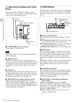
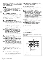
Page 13: ...ne blocks as shown below For details see the pages indicated within parentheses For information about the rear panel of the control panel see BKDF 901 Rear Panel page 19 1 External Connections and Power Block page 14 9 Display Panel Menu Control Block page 19 8 DME SETUP Block page 18 7 Numeric Keypad page 17 6 Joystick Block page 16 2 KEYER Block page 14 3 KEY DELEGATION Block page 15 4 Cross Poi...

Page 14: ...s Press one of the following buttons lighting it to select a key type EXT external key button Press to create a key by using separate signals for the key fill and key source SELF self key button Press to create a key by using the same signal for the key fill and key source CK chroma key button Press to create a chroma key b MASK button Press this button turning it on to apply a mask to a key When ...

Page 15: ...buttons select current on air background video For the functions of the various buttons see Assigning video input signals to cross point selection buttons page 76 b PRESET selection button row These buttons select the video that will be the on air background after a transition The signals that are assigned to the buttons in this row are the same as the signals that are assigned to the buttons in t...

Page 16: ...ou to control a transition manually The video changes according to the position of the fader lever as you move it up and down You can limit the effective range of the fader lever so that the transition is ended before you move it all the way to the top or bottom For information about how to limit the range see Limiting the effective range of the fader lever page 113 e DSK downstream key transition...

Page 17: ...ton Displays the menu that allows you to specify the center position of a wipe pattern To specify the center position with the joystick press this button to display the menu and then adjust the position with the joystick This button is enabled only when key is not selected as the operation target see page 15 g X Y Z parameter selection buttons Select parameters to adjust with the joystick You can ...

Page 18: ...e of internally generated color matte signals INPUT button When pressed with the SHIFT button lit displays a menu that allows you to make settings related to input signals for example make settings for assigning input signals to a bus MV multi view button When pressed with the SHIFT button lit displays a menu that allows you to select the number of child windows in the optional multi view display ...

Page 19: ...ameters Useful supporting information for menu operations may appear in the upper right b F1 to F4 knobs The F1 to F4 adjustment knobs are located beneath the parameter display area They correspond to up to four parameters per menu You can set parameter values by rotating the knobs or by pressing a knob and entering the value for the corresponding parameter in the numeric keypad Instead of specify...

Page 20: ...e wiring that might have excessive voltage to this port Follow the instructions for this port Par mesure de sécurité ne raccordez pas le connecteur pour le câblage de périphériques pouvant avoir une tension excessive à ce port Suivez les instructions pour ce port Aus Sicherheitsgründen nicht mit einem Peripheriegerät Anschluss verbinden der zu starke Spannung für diese Buchse haben könnte Folgen S...

Page 21: ... information about the rear panel of the control panel see BKDF 902 Rear Panel page 26 4M E Cross Point Bus Block page 23 3Key AUX Bus Control Block page 22 2KEYER Block page 14 1External Connections and Power Block page 14 qsDisplay Panel Menu Control Block page 19 qaNumeric Keypad page 17 0Joystick Block page 16 5PROGRAM PRESET Cross Point Bus Block page 23 6PROGRAM PRESET Transition Block page ...

Page 22: ... Select the output of the bus selected with the key delegation buttons or the AUX delegation buttons MV1 multi view 1 K OUT key output button Selects the multi view 1 output when pressed with the SHIFT button unlit Selects the key output of the M E bus when pressed with the SHIFT button lit MV2 multi view 2 CLN clean button Selects multi view outputs 2 when pressed with the SHIFT button unlit Sele...

Page 23: ...ection buttons page 76 b M E bus B selection button row Select the background B bus video which is output after the start of a transition For the functions of the various buttons see Assigning video input signals to cross point selection buttons page 76 About the SHIFT buttons The SHIFT buttons on the right side of each selection button rows allow you to switch between the two signals assigned to ...

Page 24: ...splay panel allowing you to select the wipe pattern b Transition range and direction buttons FADER LIMIT button Limits the effective range of the fader lever The range limitation is enabled when this button is pressed lighting it When you press the button twice to turn it on the Fader Limit menu appears in the display panel This menu allows you to specify the effective range of the fader lever as ...

Page 25: ... a DME wipe pattern To select NAM press this button while pressing the MIX button Both buttons light c Transition range and direction buttons FADER LIMIT button Limits the effective range of the fader lever The range limitation is enabled when this button is pressed lighting it When you press the button twice to turn it on the Fader Limit menu appears in the display panel This menu allows you to s...

Page 26: ... button Displays the menu for still image storage operations such as download capture and export 0 Joystick Block See descriptions for the BKDF 901 in 6 Joystick Block page 16 qa Numeric Keypad See descriptions for the BKDF 901 in 7 Numeric Keypad page 17 qs Display Panel Menu Control Block See descriptions for the BKDF 901 in 9 Display Panel Menu Control Block page 19 BKDF 902 Rear Panel Two AC I...

Page 27: ...ns of Parts On how to use each connectors and switches see descriptions in BKDF 901 Rear Panel page 19 7 POWER switches A and B 6 AC IN connectors A and B 5 Ground terminal 4 DEVICE connector 3 MAINTENANCE connector 2 PROCESSOR connector 1 EXT DISPLAY connector ...

Page 28: ...KDF 990 provides an additional power switch below the power switch of the standard power supply unit For details see Installing the BKDF 990 Power Supply Unit page 51 Rear Panel 1 I O expansion slots a I O expansion slot upper In one slot you can install two input expansion boards third and fourth boards and one output expansion board second board POWER switch and indicator 1 I O expansion slots s...

Page 29: ... the same signals as the PGM1 2 connectors They can also output other types of signals including output preview PVW signals clean CLN signals key output KeyOut signals multi view MV signals and the input signals of this unit In01 to In24 You can specify output of different signals from the AUX1 connector and the AUX2 connector Input signals In09 to In24 appear only when optional input expansion bo...

Page 30: ...ériphériques pouvant avoir une tension excessive à ce port Suivez les instructions pour ce port Aus Sicherheitsgründen nicht mit einem Peripheriegerät Anschluss verbinden der zu starke Spannung für diese Buchse haben könnte Folgen Sie den Anweisungen für diese Buchse f GPI IN GPI input connector D sub 25 pin GPI 1 signals input to this connector can be used to execute transitions and other switche...

Page 31: ...or signal settings see Specifying the signal type of DVI input signals page 85 BKDF 960 4 SDI Output Board SDI OUT SDI output 1 to 4 connectors BNC type Output SDI signals One board has four connectors and up to two boards can be installed Together with the standard SDI output signals 1 to 4 this allows you to output up to a maximum of 12 signals Connectors 1 and 2 only are equipped with internal ...

Page 32: ...0 Power Supply Unit in the lower rack of the processor unit You can then use power switch B to turn it on and off as a backup power supply For details see Installing the BKDF 990 Power Supply Unit page 51 Other Options For details about the following options see Installing Function Expansion Boards page 46 BKDF 940 2CH DME Board BKDF 950 Multi Viewer Board Connector number Connector name Output si...

Page 33: ...two REF IN connectors When you are using a reference sync signal generator and do not want to perform loop through output of the reference sync signal input to one of the REF IN connectors of the switcher attach a 75 Ω terminator to the other connector see page 29 Also use 75 Ω termination on all devices connected to the switcher The method for connecting the termination depends on the connected d...

Page 34: ...e signal input To reference signal input To reference signal input To reference signal input To reference signal input To reference signal input To SDI IN1 To SDI IN2 To SDI IN3 To SDI IN4 To SDI IN5 To SDI IN6 Reference sync signal generator To REF IN To PGM1 To PGM2 To AUX1 To AUX2 Monitor or other device with HD SDI input Recorder or other device with HD SDI input Monitor or other device with H...

Page 35: ...2 System with Editor Connected The figure below shows an example of a video editing system with a recorder multiple players signal output devices and an editor to control the other devices Connect the HD SDI output of the output devices to the SDI IN connectors of the switcher ...

Page 36: ...eference sync signal generator To REMOTE To REMOTE To REMOTE Editor To SDI IN1 To SDI IN2 To SDI IN3 To EDITOR To PGM2 To PGM1 To REMOTE Monitor or other device with HD SDI input Monitor or other device with HD SDI input Video signal Reference sync signal Control signal Player or other device with HD SDI output Player or other device with HD SDI output To AUX1 Recorder or other device with HD SDI ...

Page 37: ...ble with the analog signals of the HD15 high density 15 pin D Sub standard You can use conversion cables and adaptors to connect them to devices equipped with HDMI or HD15 connectors When you input video signals from the HDMI connectors to the switcher the switcher can receive only progressive video signals The switcher cannot process the video signals copy protected by HDCP High bandwidth Digital...

Page 38: ...r To DVI2 To HDMI connector DVI I h HDMI conversion cable To DVI1 Monitor or other device with HD15 input connector ToHD15input connector DVI I h HD15 conversion adaptor To DVI1 To DVI1 To DVI connector Projector or other device with DVI input To DVI2 To DVI connector Monitor or other device with DVI input Computer ...

Page 39: ...injury when installing and removing expansion options You can use the Status sub menu of the Setup menu to check whether expansion options are installed For details see page 170 Installing I O Expansion Boards About installation locations and channel numbers Pull out the expansion board installation trays from the I O expansion board slots lower and upper on the rear panel of the processor unit us...

Page 40: ...hanumeric characters in length For details see page 74 Input expansion board channel numbers a IN11 and IN12 are invalid b IN15 and IN16 are invalid c IN19 and IN20 are invalid d IN23 and IN24 are invalid Notes Installation position on expansion board installation tray Lower tray Upper tray Left Center Right Left Center Right Whether board can be installed Yes Yes No Yes Yes No Input number displa...

Page 41: ...screws B 3 6 securing the board tray stabilizers and remove the stabilizers 2 As shown in the figure below push the levers on each end of the expansion board installation tray to open them and then pull the tray out Installation position on expansion board installation tray Lower tray Upper tray Left Center Right Left Center Right Whether board can be installed No No Yes No No Yes Output number di...

Page 42: ...nk panel where you want to install an I O expansion board and remove the blank panel Do not discard the panels Retain them for future use If you remove an I O expansion board you will need to reattach the blank panel If you remove all I O expansion boards reattach the ventilation adjustment panel Use the screws that secured the blank panel to secure the I O expansion board For details see step 5 K...

Page 43: ...heat transfer sheet 2Hold the bottom side of the heat transfer sheet the side from which you removed the adhesive cover sheet down and affix it to the expansion board installation tray aligning it with the positioning guide frame on the expansion board installation tray I O expansion board heat transfer sheet affixation position shaded part BKDF 910 Positioning guide frames for input expansion boa...

Page 44: ...driver to tighten the screws Set the tightening torque to 0 59 N m For the installation positions of expansion boards see page 39 6 Use the following procedure to attach the connector name plate supplied with the expansion board 1Using the screws see the following table supplied with the expansion board secure the connector name plate to the expansion board Notes For input expansion boards For out...

Page 45: ...ert the expansion board installation tray into its original slot and align the notches of the levers on both sides of the tray to the left and right sides of the slot mouth 8 As shown in the figure below lock the tray by pulling the tray levers toward the inside The tray is pushed all the way into the slot and locked in place Expansion board Screws Tightening torque BKDF 910 BKDF 911 BKDF 960 BKDF...

Page 46: ...sor unit and install the function expansion boards on the standard I O module Insert the expansion board connectors into the sockets on the standard I O module and secure them with the screws supplied with the expansion boards Connect the BKDF 940 to the DME1 and DME2 sockets and connect the BKDF 950 to the MV1 and MV2 sockets Yes Can be installed No Cannot be installed Function expansion board So...

Page 47: ...nstall function expansion boards 1 Remove the four screws B 3 6 securing the board tray stabilizers and remove the stabilizers 2 As shown in the figure below push the levers on each end of the standard I O module to open them and then pull the standard I O module out Standard I O module MV1 socket DME1 socket MV2 socket DME2 socket ...

Page 48: ...DF 940 to the function expansion board 1Remove the adhesive surface cover sheet from one side only of the heat transfer sheet 2Hold the bottom side of the heat transfer sheet the side from which you removed the adhesive cover sheet down and affix it to the standard I O module aligning it with the positioning guide frame on the standard I O module Positioning guide frames ...

Page 49: ...wn until the connector is coupled into the socket For the installation location of each expansion board see page 46 5 Using the four M3 screws supplied with the function expansion board secure the expansion board to the signal processing board of the standard I O module Use a torque screwdriver to tighten the screws Set the tightening torque to 0 59 N m 3Remove the adhesive surface cover sheet fro...

Page 50: ...s original slot and align the notches of the levers on both sides of the board to the left and right sides of the slot mouth 7 As shown in the figure below lock the standard I O module by pulling the levers toward the inside The standard I O module is pushed all the way into the slot and locked in place ...

Page 51: ...emove function expansion boards Carry out the installation procedure in reverse Installing the BKDF 990 Power Supply Unit To install the BKDF 990 Remove the front panel of the processor unit remove the internal blank panel and then install the BKDF 990 1 Remove the two screws securing the front panel of the processor unit and remove the panel ...

Page 52: ...wo screws B 4 8 securing the blank panel inside the processor unit and remove the blank panel 3 Insert the BKDF 990 into the installation slot inside the processor unit and push it all the way in 4 Using the two screws removed in step 2 secure the BKDF 990 to the processor unit ...

Page 53: ...nal Expansion Boards Chapter 3 Preparations 5 Using the two screws removed in step 1 attach and secure the front panel To remove the BKDF 990 Power off the BKDF 990 and then carry out the installation procedure in reverse ...

Page 54: ...he BKDF 902 change the setting of a DIP switch on the external device interface connectors board in the processor unit When using the BKDF 901 you need not perform the following procedure 1 Remove the four screws B 3 6 securing the board tray stabilizers and remove the stabilizers 2 As shown in the figure below push the levers on each end of the external device interface connectors board to open t...

Page 55: ...witch under the flat cable to the ON position Do not change settings of the other pins 4 Insert the external device interface connectors board into its original slot and align the notches of the levers on both sides of the board to the left and right sides of the slot mouth Note ...

Page 56: ... Preparations 5 As shown in the figure below lock the board by pulling the levers toward the inside The board is pushed all the way into the slot and locked in place 6 Using the four screws removed in step 1 attach the board tray stabilizers ...

Page 57: ...uired when the BKDF 990 is installed Always power off all devices before connecting If you will not be connecting the BKDF 990 connect the AC power cord of the processor unit to the upper AC IN connector If you want to attach the supplied rack mounting bracket to the control panel refer to the figure on page 215 for the attachment position Use the screws supplied with the rack mounting bracket to ...

Page 58: ...1 control panel To PROCESSOR Control cable supplied Processor unit To PANEL AC power cord not supplied To AC IN To AC power AC power cord not supplied To AC IN To AC power BKDF 902 control panel To PROCESSOR Control cable supplied Processor unit To PANEL AC power cord not supplied To AC IN To AC power AC power cord not supplied To AC IN To AC power To AC IN AC power cord not supplied To AC power ...

Page 59: ...n using the BKDF 901 or the POWER switches A and B when using the BKDF 902 on the rear panel of the control panel The control panel is powered on and the panel buttons and display panel light The control panel enters boot mode after the power is turned on Several minutes are required before the control panel can be operated When the control panel exits boot mode the following information appears i...

Page 60: ...d the processor unit 3 Pull the fader lever once from the top of its range all the way to the bottom 4 Power on the peripheral devices To power off Always use the following procedure to power off If you power off without carrying out the correct procedure the current control panel settings will not be saved and the switcher may become unable to boot normally If you have connected a USB flash drive...

Page 61: ...Press the SHUTDOWN button The following message appears in the display panel 2 Press the F2 knob Shutdown processing storage of the various settings begins When storage of the setting ends the following message appears in the display panel BKDF 902 BKDF 901 ...

Page 62: ...essing If you turn off the power before the shutdown finishes the switcher may become unable to boot normally 3 Turn off the POWER switch when using the BKDF 901 or the POWER switches A and B when using the BKDF 902 on the rear panel of the control panel 4 Turn off the POWER switch on the processor unit Note ...

Page 63: ...set of transitions and effects can be recalled and used as required Setup system settings menu Allows you to make basic system settings such as video format selection and signal assignments to I O connectors Specific function settings and adjustments are made in the sub menus beneath each menu Sub menus with many setting items have a hierarchical structure For a list of the sub menus beneath each ...

Page 64: ...nterclockwise Decrease a setting value or display the previous setting item Press when numeric input is required Enter numeric keypad mode Some knob may return a setting to its factory default value when it is pressed and held for one second or longer Menu Operations in the GUI Menus You can connect a PC monitor and a USB mouse to the switcher This allows you to select items in menus and sub menus...

Page 65: ...r panel of the control panel and connect a USB mouse to the DEVICE connector on the rear panel of the control panel Connecting a touch panel monitor Connect the video input connector of the monitor to the EXT DISPLAY connector on the rear panel of the control panel and connect the USB connector of the monitor to the DEVICE connector on the rear panel of the control panel PC monitor To video input ...

Page 66: ... time 1 When using the BKDF 901 If the SHIFT button of the DME SETUP block is not lit press it to light it When using the BKDF 902 Skip to step 2 2 Press the SYSTEM button A settings sub menu of the System sub menu appears in the display panel 3 Press the h or H button in the numeric keypad until the Update sub menu appears Update appears in the sub menu title display area If it is already display...

Page 67: ...he bottom right corner of the screen 6 Press the center point of the calibration mark in the bottom right corner of the screen The mark disappears when you press it and another mark appears in the upper right corner of the screen 7 Press the center point of the calibration mark in the upper right corner of the screen A confirmation message appears asking whether you have finished the calibration ...

Page 68: ...ce that a touch position is different from the display position GUI menu screen configuration a Menu category section Displays tabs menu selection tabs for each of the five categories in the basic menu configuration see page 63 When you select a tab the sub menus for that menu appear in the sub menu section 2 b Sub menu section Displays tabs for the sub menus in the menu that was selected in the m...

Page 69: ...em directly To make sub menu settings 1 In the menu category section select a menu tab Tabs for the sub menus in that menu appear in the sub menu section 2 Select the tab of the sub menu that you want to set The sub menu is selected and its current settings appear in the parameter section If the sub menu has a number of levels you can display the settings for a deeper sub menu by touching its tab ...

Page 70: ...nu screens differ from the names that appear in the display panel of the control panel See page 176 for a list of menus and their names as they appear in GUI menu screens and the display panel Note F1 knob operation area F2 knob operation area F3 knob operation area F4 knob operation area ...

Page 71: ...ed by the switcher 1 When using the BKDF 901 If the SHIFT button of the DME SETUP block is not lit press it to light it When using the BKDF 902 Skip to step 2 2 Press the SYSTEM button A settings sub menu of the System sub menu appears in the display panel 3 Press the h or H button in the numeric keypad until the Type video format selection sub menu appears Type appears in the sub menu title displ...

Page 72: ... to restart the switcher On how to power the switcher off see To power off page 60 7 Rotate the F4 knob to set the system delay Normal The frame synchronizers for the input connectors see page 79 are enabled automatically Min Minimum System delay is held to the minimum If the frame synchronizers for the input connectors are disabled the delay with respect to the reference sync signal is 1H The amo...

Page 73: ...tings Use the following procedure to specify a reference sync signal input to the switcher and a reference sync signal generated and output by the switcher 1 When using the BKDF 901 If the SHIFT button of the DME SETUP block is not lit press it to light it When using the BKDF 902 Skip to step 2 2 Press the SYSTEM button A settings sub menu of the System sub menu appears in the display panel 3 Pres...

Page 74: ...alphanumeric characters long To change the names save a text file containing a list of the current signal names to a USB flash drive edit the names on a computer and then load the edited list into the switcher Signals have the following display names when the switcher is shipped from the factory Knob Parameter Description Setting range F1 Ref I Input reference sync signal BB Black burst signal Tri...

Page 75: ...put input signal settings sub menu appears in the display panel 4 Press the h or H button in the numeric keypad until the Signal Rename sub menu appears Signal Rename appears in the sub menu title display area If it is already displayed there you can skip this step 5 Hold the F1 knob down for one second or longer A file containing a list of the signal names dfs900 ini is saved in the root director...

Page 76: ...epending on the board are invalid For information about channel numbers of input expansion board see page 40 8 Save the edited name file to the USB flash drive overwriting the old file and then insert the USB flash drive into the USB MEMORY connector 9 Repeat steps 2 to 4 to display the Signal Rename sub menu and then hold the F4 knob down for one second or longer The edited file is read into the ...

Page 77: ... four color matte signals four still images and a black signal The following signals are assigned when the switcher is shipped from the factory Tip PROGRAM PRESET selection buttons Video signals Video signals specified with SHIFT button BLACK Black signal Black signal 1 to 8 Signals connected to the SDI IN1 to IN8 connectors Signals connected to optional input expansion boards 9 Still image 1 Colo...

Page 78: ...n the sub menu title display area If it is already displayed there you can skip this step 4 When using the BKDF 901 In the PRESET selection button row press the button to which you want to assign a signal When using the BKDF 902 In the M E bus B selection button row press the button to which you want to assign a signal If you press the SHIFT button before pressing the button to which you want to a...

Page 79: ...ill images from input signals and use those images in place of normal video input When SDI signals SD SDI or HD SDI are being input and it is selected to output ancillary data page 89 no ancillary data will be output if the frame synchronizers for the corresponding input channels are enabled To output ancillary data disable the frame synchronizers To enable frame synchronizers 1 When using the BKD...

Page 80: ...ronizer is enabled for input video signals All settings other than Live are settings for capture of still images from input signals For details see To capture still images from input signals page 80 7 Repeat steps 4 to 6 as required to set other inputs To capture still images from input signals In step 6 of To enable frame synchronizers page 79 select an item other than Live and make the settings ...

Page 81: ... video format is switched from HD to SD the up converter settings of each input channel are set automatically to OFF Make the up converter settings again when you return the video format to HD The following table lists the input channels on the input expansion boards that are equipped with up converters For more information about the channel numbers for channels with up converters and how they are...

Page 82: ...title display area If it is already displayed there you can skip this step 4 When using the BKDF 901 Press the PRESET selection button that selects the input you want to set If you want to set an input that has been assigned by using the SHIFT button see page 76 press the SHIFT button before pressing the PRESET selection button When using the BKDF 902 Press the M E bus B selection button that sele...

Page 83: ... an HDTV size still image The left and right sides of the picture will not be displayed normally if no image is downloaded or if the downloaded image is a SDTV size image Specifying the signal type of analog input signals When you are using the optional BKDF 911 2 SD Video Input Board specify the signal type of the analog signals that will be input to the board For more information about the BKDF ...

Page 84: ...ess the M E bus B selection button that selects the analog input that you want to set If you want to set an analog input that has been assigned by using the SHIFT button see page 76 press the SHIFT button before pressing the M E bus B selection button 5 Rotate the F2 knob to select the type of signal that will be input Compst Analog composite signal Y CB CR Analog component color difference signal...

Page 85: ...age 39 Depending on the video format setting of this switcher page 71 select the DVI input signal resolution from the values in the following table If you specify a resolution other than the values shown in the table images may be unable to be reproduced normally Y CB CR COMP Y Luminance Y signal IN09 IN13 IN17 IN21 B Y Color difference B Y signal R Y Color difference R Y signal COMP Composite sig...

Page 86: ...rea If it is already displayed there you can skip this step 4 When using the BKDF 901 Press the PRESET selection button that selects the DVI input you want to set If you want to set a DVI input that has been assigned by using the SHIFT button see page 76 press the SHIFT button before pressing the PRESET selection button When using the BKDF 902 Press the M E bus B selection button that selects the ...

Page 87: ...picture are displayed the vertical and horizontal modification ratios are different Application of conversion settings of step 5 to identical picture If you select Normal when the switcher s video format is set to HD signals see page 71 black is added at the top bottom left and right of the picture However the top and bottom of the picture are cut if the input video is UXGA or WUXGA If you select ...

Page 88: ...tton before pressing the PRESET selection button When using the BKDF 902 Press the M E bus B selection button or the PRESET bus selection button that selects the input you want to set If you want to set an input that has been assigned by using the SHIFT button see page 76 press the SHIFT button before pressing the M E bus B selection button or the PRESET bus selection button 5 Rotate the F1 to F4 ...

Page 89: ...rd in the processor unit When the input is SDI signals HD SDI or SD SDI you can select whether to output ancillary data such as multiplexed audio and timecode The signals output from the PGM1 and PGM2 outputs cannot be changed 1 When using the BKDF 901 Press the AUX button When using the BKDF 902 Press one of the AUX1 to AUX10 buttons The AUX3 to AUX10 buttons that correspond to channels on instal...

Page 90: ...review output when using the BKDF 902 If after step 3 you rotate the F3 knob to set the Inh Inhibit item to On the AUX output signal cannot be changed from the control panel Control is possible only by remote control from an optional AUX BUS remote controller For more information about screen settings for multi view output see page 96 When optional input expansion boards have been installed signal...

Page 91: ...video format see page 71 is set to HD signals When the video format is switched from HD to SD the down converter settings of each input channel are set automatically to OFF Make the down converter settings again when you return the video format to HD The following table lists the output channels on the output expansion boards that are equipped with down converters For more information about the ch...

Page 92: ...s the AUX output that you want to set from among AUX03 to AUX10 When using the BKDF 902 Skip to step 4 AUX1 and AUX2 are not provided with down converting capability 4 Rotate the F3 knob to select the conversion mode 4 3 Output with 4 3 aspect ratio edge cropped output SQ Output as squeeze video LB Output as letterbox video Off Do not down convert Specifying the signal type of analog output signal...

Page 93: ...e display area If it is already displayed there you can skip this step 3 When using the BKDF 901 Rotate the F1 knob to select an item from among AUX03 to AUX10 to which analog output has been assigned When using the BKDF 902 Skip to step 4 4 Rotate the F2 knob to select the output signal type Compst Analog composite signal Y CB CR Analog component color difference signal GBR wSync Analog component...

Page 94: ...f the DVI signals that will be output from the board For more information about the BKDF 962 see page 31 For information about how to install it see page 39 Setting of step 4 Name of BKDF 961 connector Output signal BKDF 961 installation position and channel number Lower tray Upper tray Left Left Compst COMP Y Composite signal AUX03 AUX07 B Y a R Y a COMP Composite signal AUX04 AUX08 Y CB CR COMP ...

Page 95: ... the sub menu title display area If it is already displayed there you can skip this step 3 When using the BKDF 901 Rotate the F1 knob to select an item from among AUX03 to AUX10 to which DVI output has been assigned When using the BKDF 902 Skip to step 4 4 Rotate the F2 knob to select the output signal type from the types listed in the following table BKDF 901 BKDF 902 Parameter Output signal Vide...

Page 96: ...60Hz When the system format of the output destination is 60 Hz 50Hz can be selected only when the switcher s video format see page 71 is set to 625 50 720 50 or 1080 50 This setting affects only digital signals output from the BKDF 962 Making multi view output settings The multi view function is available when you install the optional BKDF 950 Multi Viewer Board in the processor unit By assigning ...

Page 97: ...t a key signal and so on For details about the BKDF 950 and information about how to install it see page 46 The MV1 Window and MV2 Window sub menus cannot be set if the BKDF 950 board is not installed To specify the partition type and assign output video to child windows 1 When using the BKDF 901 If the SHIFT button of the DME SETUP block is not lit press it to light it When using the BKDF 902 Ski...

Page 98: ...6 5 Rotate the F2 knob to select the number of the child window that you want to set Depending on the number of partitions selected in step 4 select a number from 1 to 16 For more information about partitions in the multi view screen and child window numbers see page 99 6 Rotate the F3 knob to select the video output to the child window BLK Black signal IN01 to IN24 Video inputs STL1 to STL4 Still...

Page 99: ... window titles is turned off automatically when you change the multi view window partition type If you want to display titles turn title display on again Multi view window partition types and child window numbers To adjust the display positions and sizes of child window titles 1 Carry out steps 1 to 6 of the procedure in Changing signal display names page 74 to load a list file output by the contr...

Page 100: ...to 3 of the procedure in To specify the partition type and assign output video to child windows page 97 to display the MV1 or MV2 sub menu and then carry out step 8 to turn the display of child window titles on LargeHeight Specifies the height of characters in large child windows 0 to 50 SmallOffsetV Specifies the vertical display position in small child windows 0 to 25 SmallOffsetH Specifies the ...

Page 101: ...KDF 902 Skip to step 2 2 Press the MV button A settings sub menu of the MV multi view output settings sub menu appears in the display panel 3 Press the h or H button in the numeric keypad until one of the following status sub menus appears for one of the types of windows to which frames can be added If the sub menu that you want is already displayed you can skip this step Tips Child window output ...

Page 102: ...to program output next or component elements of that output MV2 OA Tally Among the multi view child windows displayed by a BKDF 950 connected to MV2 socket display a frame around windows that display the current On Air program output or component elements of that output MV2 Next Tally Among the multi view child windows displayed by a BKDF 950 connected to MV2 socket display a frame around windows ...

Page 103: ...the AUX1 to AUX10 buttons When optional expansion boards are not installed the AUX3 to AUX10 buttons are disabled A settings sub menu of the Aux sub menu appears in the display panel 3 Press the H button in the numeric keypad until the Setup Output Other sub menu appears Other appears in the sub menu title display area If it is already displayed there you can skip this step 4 Rotate the F1 knob to...

Page 104: ... it When using the BKDF 902 Skip to step 2 2 Press the SYSTEM button A settings sub menu of the System sub menu appears in the display panel 3 Press the h or H button in the numeric keypad until the Other sub menu appears Other appears in the sub menu title display area If it is already displayed there you can skip this step 4 Rotate the F4 knob to select the timing of video switching Odd Switch v...

Page 105: ...DF 902 Skip to step 2 2 Press the SYSTEM button A settings sub menu of the System sub menu appears in the display panel 3 Press the h or H button in the numeric keypad until the Other sub menu appears Other appears in the sub menu title display area If it is already displayed there you can skip this step 4 Rotate the F3 knob to select the timing of video switching Moment Selects the SHIFT side fun...

Page 106: ...he System sub menu appears in the display panel 3 Press the h or H button in the numeric keypad until the Date Adj set date sub menu appears Date Adj appears in the sub menu title display area If it is already displayed there you can skip this step 4 Rotate the F2 F3 and F4 knobs to set the year month and day The correspondence between knobs and parameters is as follows 5 Hold the F1 knob down for...

Page 107: ...pears in the sub menu title display area 7 Rotate the F2 F3 and F4 knobs to set the hour minute and second The correspondence between knobs and parameters is as follows 8 Hold the F1 knob down for one second or longer The time is set Knob Parameter Description Setting range F2 H Hour 0 to 23 F3 M Minute 0 to 59 F4 S Second 0 to 59 ...

Page 108: ...ton to select the video which was selected in the M E cross point bus block The pressed button lights in red This indicates that the selected video is being output as the program video In the multi view screen the current program output video is surrounded by a frame When the switcher is shipped from the factory the color of the frame is set to red To select the background that appears after a tra...

Page 109: ...used effect types are mixes and wipes This section explains how to switch the background Cutting to a New Background Basic cut operations There are two ways to cut to a new background Cut directly to the next background by pressing a cross point selection button Check the next background in the preview screen and then press the CUT button The figure below shows the flow of cut operations Cutting d...

Page 110: ... the cross point block change to reflect the switch Example When PROGRAM selection button 1 and PRESET selection button 4 are selected Each time the CUT button is pressed the program output video switches between the video signals selected with the PROGRAM selection button and PRESET selection button When using the BKDF 902 1 In the M E transition block press the BKGD next transition selection but...

Page 111: ...evice 3 While holding down the WIPE transition type selection button press the DME button CG Wipe is selected 4 Turn on the key that uses the signal input from the playback device 5 Press the CUT button Using Transitions to Switch to the Next Video Mix and Wipe Instead of cutting instantly to the next video you can reveal it gradually by applying a variety of video effects This switcher provides t...

Page 112: ...using the BKDF 901 or the REV button when using the BKDF 902 Press the REVERSE button when using the BKDF 901 or the REV button when using the BKDF 902 lighting it to cause transitions to proceed in the reverse direction Press the button again turning it off to cause transitions to proceed in the normal forward direction Using the NORM REV button Press the NORM REV button lighting it to select alt...

Page 113: ...ader lever to the desired position and release the KEY SRC button Switching with Mix Transitions Mixes are transitions in which the next video fades into the original video finally replacing it You can choose from among the following three types of mix transitions MIX transition This is a transition in which the original video gradually fades out while the next video gradually fades in At the midp...

Page 114: ...mix transition is executed between the two currently selected video signals When using the BKDF 902 1 In the M E transition block press the BKGD next transition selection button lighting it 2 Press an M E bus A selection button in the M E cross point bus block or a PROGRAM bus selection button in the PROGRAM PRESET cross point bus block to select the video that appears before the cut 3 Press an M ...

Page 115: ...point bus block press a PRESET selection button to select the video that appears after the transition 4 Press the WIPE or DME transition type selection button lighting it The WIPE menu or the DME menu appears in the display panel WIPE menu DME menu DME must be enabled to use DME wipe patterns Pressing the DME button when DME is not enabled has no effect To enable and disable DME press the DME ENAB...

Page 116: ...IPE button of the PROGRAM PRESET transition block is pressed the P P WIPE menu appears in the display panel P P WIPE menu DME must be enabled to use DME wipe patterns Pressing the DME button when DME is not enabled has no effect To enable and disable DME press the DME ENABLE button see page 14 in the KEYER block 5 Rotate the F1 knob to select a wipe pattern or DME pattern To select by entering a p...

Page 117: ...tte4 can be assigned to the cross point selection buttons allowing you to use them as backgrounds in keys and as modifiers You can change the colors of these color matte signals Assigning Color Mattes to Cross Point Selection Buttons Use the menu system to assign color mattes to the desired buttons For details see Assigning video input signals to cross point selection buttons page 76 Changing the ...

Page 118: ...l has been assigned and then execute the transition For details about how to execute background transitions see Switching Backgrounds page 109 Using Internally Stored Still Images The switcher is equipped with internal memory for the storage of still image files You can use images stored in this memory in transitions and compositions The supported still image file formats include 24 bit JPG jpeg a...

Page 119: ...le frame synchronizers see Using the internal frame synchronizers page 79 b An asterisk appears after still image files that have already been stored If you have changed the display names of input signals and internal signals see page 74 those names appear in the F1 knob operation area 7 Press the F4 knob and hold it down for one second or longer Downloading from the USB flash drive starts During ...

Page 120: ...ls see page 74 those names appear in the F1 knob operation area 4 Press the F4 knob and hold it down for one second or longer Downloading to the internal still image memory starts During the download the STILL button lights in red When the download finishes the button returns to lit in orange Using Stored Still Images in Background Transitions Images stored in still image memory can be used in bac...

Page 121: ...to switch to the Export Still sub menu 5 Set the parameters a Overwrite appears in the F3 knob operation area if a file with the same number already exists on the USB flash drive and New File appears if no file with the same number exists 6 Press the F4 knob and hold it down for one second or longer Export to the USB flash drive starts During the download the STILL button lights in red When the do...

Page 122: ...ing Keys to Compose Video This switcher allows you to add four keys KEY1 to KEY4 and two downstream keys DSK1 and DSK2 to the background video Key types The following three key types are available on this switcher External keys EXT Keys that use separate signals for key fill and key source Self keys SELF Keys that use the same signal for key fill and key source Chroma keys CK Unlike the two keys d...

Page 123: ...ample chroma keys are used to create video of foreground subjects against an arbitrary background by shooting the subjects against a blue background extracting only the subjects for use as a key fill signal and inserting the key fill signal into the background Chroma keys can be used only with KEY1 to KEY4 They cannot be used with DSK1 and DSK2 The normal procedure for creating a chroma key is to ...

Page 124: ...play panel At the same time a cross cursor appears in the preview or program output video You can reselect the signal to use in the chroma key by rotating the F1 knob 5 Using the joystick move the cross cursor to the color that you want to cut out keying color Instead of using the joystick you can also use the F2 and F3 knobs to adjust 6 Press the AUTO CK button An auto chroma key is created To ad...

Page 125: ...e C1 setting is ignored when C2 is anything other than 0 00 To adjust key opacity Use the Other sub menu to adjust the opacity of chroma keys The Other sub menu has the following parameter SAT 100 Hue of keying color Angle Area removed by chroma key Adjust with C2 Adjust with C1 C1 Small C1 Large C2 Small C2 Large Parameter group 1 4 Knob Parameter Description Settings F2 Hue Keying color hue 0 0 ...

Page 126: ... in the numeric keypad until the Other sub menu appears Other appears in the sub menu title display area If it is already displayed there you can skip this step 4 Rotate the F1 knob to select PGM or PVW When using the BKDF 901 When using the BKDF 902 Inserting Keys by a Cut Transition 1 Set up the key signal For information about how to set up keys see Setting Up Keys page 122 BKDF 902 BKDF 901 Kn...

Page 127: ...ition 2 Press the MIX button lighting it 3 Set the transition rate as required For information about how to set transition rates see Setting Transition Rates page 117 4 Use an AUTO TRANS button or the fader lever to execute the mix transition For information about how to execute a transition see Using Transitions to Switch to the Next Video Mix and Wipe page 111 Inserting Keys by a Wipe or DME Wip...

Page 128: ...E wipe patterns for each key Select the desired key and then press the DME button again The DME menu for the operation target key selected in the KEY appears 5 Rotate the F1 knob to select a wipe pattern or a DME wipe pattern To select by entering a pattern number press the F1 knob enter the number in the numeric keypad and then press the ENTER button For pattern numbers see Wipe page 189 and DME ...

Page 129: ... when using the BKDF 901 or in the key AUX bus control block when using the BKDF 902 select the target key of the operation 2 Press the DME ENABLE button in the KEYER block lighting it For more information about the function of this button see page 14 3 When using the BKDF 901 Press the SHIFT button in the DME SETUP block lighting it When using the BKDF 902 Skip to step 4 4 Press a DME setting but...

Page 130: ...stream key and turn the button off Inserting Downstream Keys with a Mix 1 Set up the key signal For information about how to set up keys see Setting Up Keys page 122 2 Set the transition rate for downstream keys For information about how to set transition rates see Setting Transition Rates page 117 3 Press the DSK1 or DSK2 AUTO TRANS button The transition is executed at the specified transition ra...

Page 131: ...using the BKDF 901 or in the DSK fade to black control block when using the BKDF 902 The video being output to program output fades out according to the specified transition rate and is replaced by a black screen If you press the FTB button once more after the fade to black finishes the switcher executes a transition back to the original video If you press the FTB button during a fade to black the...

Page 132: ...attern For example you can add borders to a pattern or modify the pattern s shape or position Customized patterns can be registered as user patterns Border example For information about how to select wipe patterns see Switching with Wipe and DME Wipe Transitions page 115 or Inserting Keys by a Wipe or DME Wipe Transition page 127 Adding Borders to Wipe Patterns You can add borders by adjusting the...

Page 133: ... Press the F2 knob and hold it down for one second or longer The pattern is registered under the number selected in step 3 To unregister a pattern Rotate the F1 knob in the Display Panel Menu Control Block to select the pattern number to unregister and then press the F4 knob and hold it down for one second or longer Operation Knob Parameter Settings Set the border width F2 Wid Border Width 0 0 to ...

Page 134: ...menu to do the following a Shown only in GUI menu screens b xxx M E DME appears if you are setting up a transition and Keyer appears if you are setting up a key To display the DME Basic sub menus When using the BKDF 901 Press the SHIFT button of the DME SETUP block turning it off and then press the BASIC button When using the BKDF 902 Press the BASIC button in the DME SETUP block The most recently...

Page 135: ...f images differ depending on the coordinates in which they are defined To adjust parameters in the Position and Rotation sub menus select the coordinates by selecting the following sub menus xxx M E DME appears when you are operating on a transition and Keyer appears when you are operating on a key xxx L Source Local Source sub menu Change positions and angles in source coordinates xxx L Target Lo...

Page 136: ...d Z axis Operation Knob Joystick Parameter Settings Set the X coordinate horizontal position of the image F2 Move left and right PX Position X 8 000 to 8 000 Set the Y coordinate vertical position of the image F3 Move up and down PY Position Y 8 000 to 8 000 Set the Z coordinate depth position of the image F4 Rotate clockwise counterclockwise PZ Position Z 8 000 to 8 000 Operation Knob Joystick Pa...

Page 137: ...ttings Specify the crop width for the left side F1 L Left Side 0 0 to 100 0 Specify the crop width for the right side F2 R Right Side 0 0 to 100 0 Specify the crop width for the top side F3 T Top Side 0 0 to 100 0 Specify the crop width for the bottom side F4 B Bottom Side 0 0 to 100 0 Operation Knob Parameter Settings Enable or disable DME same function as the DME ENABLE button in the KEYER block...

Page 138: ...sible to adjust the widths of the left right top and bottom edges independently Set any one of the parameter values For information about beveled edge settings see Bevel Color sub menu parameters page 139 xxx Bevel Color a Bevel Color Select whether to add three dimensional beveled edges to an image and adjust the color of the beveled edges if added xxx Border HL a Hilight Setup Specify the direct...

Page 139: ...e color type chroma control Trail effect Adds trail like afterimages Chroma control Allows you to change the color type of images to sepia black and white or negative Operation Knob Parameter Settings Adjust the softness of the inner side of the border F1 InS Inner Softness 0 to15 Adjust the softness of the outer side of the border F2 OutS Outer Softness 0 to15 Note Operation Knob Parameter Settin...

Page 140: ...ub menus of the Warp sub menu to do the following Sub menu Operation Trail a Make trail effect settings Chroma Control Change the color type Operation Knob Parameter Settings Selects whether to add a trail effect F1 Typ Trail Type Off Do not add Decay Add Star Afterimage disappearing as stardust Adjusts the length of the afterimages F2 Len Length 1 to 6 Operation Knob Parameter Settings Adjusts th...

Page 141: ...ides the video into separate segments 232 to 241 Mirror a Adjust the parameters of the Mirror effect 242 to 249 xxx Defocus c Defocus Adjust the parameters of the Defocus effect which blurs the overall video image 252 Sub menu Operation Operation target pattern numbers Operation Knob Parameter Settings Select the ripple type F1 Typ Shape Type Hor Horizontal waves Ver Vertical waves Rot Rotating wa...

Page 142: ...dinate of the center of the swirl F2 PX Position X 8 000 to 8 000 Specify the Y coordinate of the center of the swirl F3 PY Position Y 8 000 to 8 000 Specify the amount of swirling F4 Amt Amount 1 000 to 1 000 Operation Knob Parameter Settings Select the type of Mosaic effect F1 Typ Type Nor Normal mosaic Rot Rotated mosaic Specify the aspect ratio of one tile F2 Asp Aspect 8 000 to 8 000 Specify ...

Page 143: ... of the lens F2 Rot Rotation 8 000 to 8 000 Specify the number of apex points when Poly or Star is selected F3 Pnt Points 1 to 16 Specify the lens focal distance F4 Amt Amount 8 000 to 8 000 Operation Knob Parameter Settings Select the pattern F1 Typ Type Rnd Round Lin Linear Mul Multi Specify the X coordinate of the lens F2 PX Position X 8 000 to 8 000 Specify the Y coordinate of the lens F3 PY P...

Page 144: ... turn the page up F1 Typ Type Turn Page Turn Roll Page Roll Specify the X coordinate of the center position of the page turn F2 PX Position X 8 000 to 8 000 Specify the Y coordinate of the center position of the page turn F3 PY Position Y 8 000 to 8 000 Specify the number of segments in the turn F4 Num Num_ Segment 3 to 31 Operation Knob Parameter Settings Specify the radius of the turn F2 Rad Rad...

Page 145: ...nce between the parts when dividing into a spiral F3 Spl Spiral 8 000 to 8 000 Adjust the displacement between parts when parts are staggered F4 Stg Stagger 8 000 to 8 000 Operation Knob Parameter Settings Specify the number of divisions when Multi is selected F1 Num Num_ Segment 3 to 31 Specify the X coordinate of the center point of the division when Multi is selected F2 PX Position X 8 000 to 8...

Page 146: ...t 2 sub menus each have two pages To switch between pages press the h and H buttons in the numeric keypad xxx M E DME appears if you are setting up a transition and Keyer appears if you are setting up a key xxx L1 xxx L2 Position Position Lxxx L1 xxx L2 Color Color Operation Knob Parameter Settings Adjust the amount of blurring F4 Amt Amount 0 to 100 Sub menu Operation xxx DME L Type a Type Select...

Page 147: ...pattern number to unregister and then press the F4 knob and hold it down for one second or longer Applying Masks to Keys You can use mask patterns to hide defects or unneeded parts of keys Use the Key Mask sub menu of the Keyer menu to select mask patterns and to specify the location and size of the pattern Box masks are the only masks that can be applied to downstream keys see page 150 Other mask...

Page 148: ...yer menu to add various types of edges to keys Edge example Shadow Edges cannot be added when you have selected chroma key as the key type and edges cannot be added to downstream keys To enable shadow edges Operation Knob Parameter Settings Select a pattern F1 Pat Mask Pattern 0 to 33 38 to 40 42 to 48 65 to 69 75 to 79 85 to 94 105 to 114 Specify the X coordinate of the center point of the patter...

Page 149: ...edge width and softness Edge Color Color Adjust the edge color Edge Position Position Adjust the edge position Operation Knob Parameter Settings Select the edge type F1 Typ Type Normal Normal edges Outline Outline Extrude Drop shadow Shadow Shadow Adjust the edge width F2 Wid Width 1 to 8 Adjust the edge softness amount of blurring F3 Sft Softness 0 0 to 100 0 When Extrude is selected specify the ...

Page 150: ...ks press the DSK1 or DSK2 button in the key AUX bus control block lighting it 2 Press the MASK button in the KEYER block lighting it Box mask is enabled and the Box Mask sub menu appears in the display panel To adjust the position of the box mask Adjust the parameters of the Box Mask sub menu BKDF 901 BKDF 902 Operation Knob Parameter Settings Specify the position of the left edge of the box mask ...

Page 151: ... also register sequences consisting of up to 31 keyframes each of which represents a set of control panel settings for a single frame of video Sequences allow you to transition gradually from the settings in one keyframe to the settings in the next keyframe according to a specified interpolation mode You can save up to 100 sequences Use the Sequence Event menu see page 179 for event and sequence o...

Page 152: ...1 2 Connect a USB flash drive to the USB MEMORY connector 3 Press the F2 knob and hold it down for one second or longer All event data is stored to the USB flash drive Recalling Events Use the following procedure to recall a stored event 1 Press the EVENT button in the numeric keypad The numeric keypad enters event mode The RECALL button lights in red and the 0 to 9 dot and CANCEL buttons become e...

Page 153: ...ed in the event is the file numbers of the images in Still1 to Still4 memory Image data is not registered BKDF 901 BKDF 902 Knob Parameter Description Settings F1 BUS M E settings other than keyer settings BUS On Include M E settings other than keyer settings BUS Off Do not include M E settings other than keyer settings P P Hold Include settings other than keyer settings and PROGRAM PRESET setting...

Page 154: ...ultiple events at once by recalling them in page units To recall events in page units use the F1 knob instead of the F3 knob in step 3 of To recall all event data from a USB flash drive page 154 Rotate the F1 knob to select the page and then with the SHIFT button in the DME SETUP block when using the BKDF 901 or the KEY SRC button in the key AUX bus control block when using the BKDF 902 held down ...

Page 155: ...vents in page units You can delete multiple registered events at once by deleting them in page units In event mode select a page and then press the F4 Initial knob and hold it down for one second or longer To recall events from an editor Setting the communications protocol to GVG100 see page 162 allows specifying an E FILE event file number to recall individual events from the BVE 2000 The followi...

Page 156: ...ce memory is cleared 5 Press the INSERT button The current control panel settings are registered as the first keyframe of the sequence 6 Press the SEQ button The numeric keypad exits sequence mode 7 Create the video that you want to register as the next keyframe 8 Press the SEQ button again to switch to sequence mode and then press the INSERT button The video created in step 7 is registered as the...

Page 157: ...nce in the selected file is recalled To display the video of the first keyframe when a sequence is recalled The normal procedure for recalling a sequence does not recall the video of the first keyframe If you want to display the video of the first keyframe when a sequence is recalled proceed as follows 1 Press the SEQ button in the numeric keypad The numeric keypad enters sequence mode The most re...

Page 158: ...e following four buttons in the numeric keypad to play a sequence after recalling it Knob Parameter Description Settings F2 BUS M E settings other than keyer settings On Do not change the current settings Off Replace the current settings with the sequence settings F3 Keyer Keyer settings F4 DSK Downstream key settings BKDF 901 BKDF 902 Knob Parameter Description Settings F2 BUS M E settings other ...

Page 159: ... is the keyframe at the current display position You can press the h and H buttons to move the current keyframe The following parameters can be changed a The interval is a relative value with respect to the execution time It changes whenever the execution time changes b Setting this to On results in a pause between individual keyframes which is convenient if you want to add or delete keyframes Whe...

Page 160: ...o sequence mode 5 Press the INSERT button The newly created video is added as a new keyframe and the keyframe that was previously at that position is shifted toward the end of the sequence along with all subsequent keyframes To delete keyframes To delete a keyframe from a sequence recall the sequence and then proceed as follows 1 Press the h and H buttons to move to the position of the keyframe th...

Page 161: ... sub menu has the following sub menus To show the sub menus In the External Connections and Power block press the EDITOR button twice in quick succession The most recently used sub menu appears in the display panel To switch between sub menus press the h and H buttons in the numeric keypad Always make the communication settings in these sub menus before connecting a serial communications device Su...

Page 162: ...e serial communications device to be connected from among the following GVG100 BVS3000 HVS AUX F2 2 RS 422A port 2 GVG100 BVS3000 HVS AUX F3 3 RS 422A port 3 GVG100 BVS3000 HVS AUX F4 4 RS 422A port 4 editor GVG100 BVS3000 HVS AUX Knob Parameter Description Settings F1 1 RS 422A port 1 9600 19200 38400 F2 2 RS 422A port 2 9600 19200 38400 F3 3 RS 422A port 3 9600 19200 38400 F4 4 RS 422A port 4 ed...

Page 163: ... using the BKDF 902 P P Mix Change the PROGRAM PRESET transition type to mix only when using the BKDF 902 P P Wipe Change the PROGRAM PRESET transition type to wipe only when using the BKDF 902 DSK 1 Cut Execute a DSK 1 cut transition DSK 1 Mix Execute a DSK 1 mix transition DSK 2 Cut Execute a DSK 2 cut transition DSK 2 Mix Execute a DSK 2 mix transition FTB Execute a fade to black SEQ Play Play ...

Page 164: ... 902 G BLK Green tally to BLACK G In01 to 24 Green tally to In01 to In24 G Stl1 to 4 Green tally to Stl1 to Stl4 G Mat1 to 4 Green tally to Mat1 to Mat4 G Rsv01 to G Rsv06 or 05 2 Reserved for future expansion Play See To set the GPI output page 166 G ME Green tally to M E only when using the BKDF 902 Alarm Alarm 1 When using the BKDF 901 R Rsv01 to R Rsv07 When using the BKDF 902 R Rsv01 to R Rsv...

Page 165: ...ly Tally output pin number 1 to 32 F2 F Tally type R Blk R In01 to R In24 R Stl1 to R Stl4 R Mat1 to R Mat4 R Rsv01 to R Rsv07 G Blk G In01 to G In24 G Stl1 to G Stl4 G Mat1 to G Mat4 G Rsv01 to G Rsv06 Play Alarm Knob Parameter Description Settings F1 Tally Tally output pin number 1 to 32 GPI button BKDF 901 BKDF 902 GPI button F2 F Tally type R Blk R In01 to R In24 RStl1 to RStl4 R Mat1 to R Mat...

Page 166: ...the pins of the TALLY GPI OUT connector see Pin Assignments page 211 For more information about signal connection see Example Connection of Tally GPI Output page 214 To set the GPI output Use the Tally sub menu to select a pin from 32 pins of the TALLY GPI OUT connector and assign Play function Rotate the F1 knob to select the pin number and rotate the F2 knob to select Play For more information a...

Page 167: ...argeted All data System data and file data System data Data such as events I O settings initial values and status data File data Still image file data stored in the control panel user pattern data and sequence data To back up recall and clear data use sub menus of the Data Backup sub menu To display the Data Backup sub menus 1 When using the BKDF 901 If the SHIFT button in the DME SETUP block is n...

Page 168: ...anagement number when backup data under that number already exists on the USB flash drive If you select a number with an asterisk the existing data is overwritten when you press the F1 knob and hold it down for one second or longer To recall system data from a USB flash drive Connect a USB flash that contains backup system data rotate the F3 knob to select a system data management number Sys0 to S...

Page 169: ...a Stl Data saved as still image files Seq Data saved as sequence files Usr User pattern data 2 Rotate the F4 knob to select the memory that you want to clear USB USB flash drive connected to the USB MEMORY connector CP Memory of the switcher s control panel 3 Press the F4 knob and hold it down for one second or longer Updating the System Use the Update sub menu of the Setup menu to update the syst...

Page 170: ...llows you to check alarms software versions and the status of the option boards installed in the switcher To display the Status sub menus 1 When using the BKDF 901 If the SHIFT button of the DME SETUP block is not lit press it to light it When using the BKDF 902 Skip to step 2 2 Press the STATUS button The most recently used sub menu appears in the display panel 3 Press the h and H buttons in the ...

Page 171: ...ard Not installed F3 Displays information about the board s in the DME1 and DME2 sockets dme 2CH DME Board Not installed F4 Displays information about the board s in the MV1 and MV2 sockets mv Multi Viewer Board Not installed Knob Parameter Description Settings F1 PWR Displays information about the installed power supply unit s in the processor unit Single A Only one standard power supply unit is ...

Page 172: ...tors 2D signal input destinations For titles and so on input the same signal for left and right Signal output and connection destinations Left signals are output from PGM Out and right signals are output from AUX1 You can view 3D video by connecting these outputs to L and R input connectors of a 3D monitor Signal type Use in 3D mode Signals input to SDI IN connectors 1 to 24 For 3D separate signal...

Page 173: ...signal 6 IN 11 IN 12 Black signal Black signal 7 IN 13 IN 14 Black signal Black signal 8 IN 15 IN 16 Black signal Black signal 9 STL1 a STL1 a Color matte signal 1 Color matte signal 1 10 STL2 a STL2 a Color matte signal 2 Color matte signal 2 11 STL3 a STL3 a Color matte signal 3 Color matte signal 3 12 STL4 a STL4 a Color matte signal 4 Color matte signal 4 Cross point buttons Video signals Vide...

Page 174: ...te signals are used for left and right Signal Assignments for Using Still Images in 3D Mode When you set the still image mode to 3D the signal assignments of the cross point buttons see the table shown on the previous page are changed When using the BKDF 901 When you select 3D with the F2 knob or F3 knob the signal assignments of cross point buttons 9 and 10 or 11 and 12 are changed as follows Whe...

Page 175: ...black in the following figure When using the BKDF 902 Instead of operating with the M E Cross Point Bus block and the M E Transition block use the PROGRAM PRESET Cross Point Bus block and the PROGRAM PRESET Transition block Some buttons are not available the buttons shown in black in the following figure Operating block Unavailable buttons KEYER block DME ENBL CK MASK EDGE SHADOW EXT and SELF are ...

Page 176: ...about GUI menu screens see Menu Operations in the GUI Menus page 64 Transition Menu for Transition Wipe and DME Settings Level 1 Level 2 Level 3 Level 4 Transition Rate Rate PGM PGM Rate DSK DSK Rate FTB FTB Rate Wipe Wipe Pattern Pattern Pat Pattern No Wid Border Width Soft Border Softness Src Border Source Wipe Border Color Border Color Pat Pattern No Lum Luminance Sat Saturation Hue Hue Wipe Mo...

Page 177: ...l 7 Keyer Key1 to Key4 Key Type External Key External Key 1 1 KIns Ext Key Insert KSrc Ext Key Source GN Ext Key Gain Clp Ext Key Clip External Key 2 2 Opac Opacity Inv Key Invert Self Key Self Key 1 1 KIns Self Key Insert GN Self Key Gain Clp Self Key Clip Self Key 2 2 Opac Opacity Inv Key Invert Chroma Key CK Auto Auto KIns Key Insert PX Position X PY Position Y Auto Auto CK Manual CK Manual 1 1...

Page 178: ...tness Dir Direction Edge Color Color Lum Luminance Sat Saturation Hue Hue Edge Position Position PX Position X PY Position Y Keyer DME Patt Pattern a DME Basic a Border a Sub Effects a Warp a Light a User User Keyer DSK1 DSK2 Key Type External Key External Key 1 1 KIns Ext Key Insert KSrc Ext Key Source GN Ext Key Gain Clp Ext Key Clip External Key 2 2 Opac Opacity Inv Key Invert Self Key Self Key...

Page 179: ... Level 2 Level 3 Still Store Download Still Download Dst Destination File Source DL Download Image Capture Capture Frz Freeze Mode File File Cap Start Capture Export Still Export Fmt File Format File File Over Write a Export Export Delete Still Delete File File Del Delete Level 1 Level 2 Level 3 Level 4 Sequence Event Sequence Seq File File File Sequence Name Store Store Sequence Recall Recall Seq...

Page 180: ...SK DSK Hold Mode Event Event Data Event Data Event Select Event Page Store Store Event Recall Recall Event Initial Initialize Event Target Event Target BUS BUS Area a Keyer Keyer Area b DSK DSK Area c Still Still Area d Level 1 Level 2 Level 3 Level 4 Level 5 Setup Matte Color Matte Color Select Lum Luminance Sat Saturation Hue Hue Input Setting1 Setting1 Src Source Assign FS FS Mode Frz Freeze Mo...

Page 181: ...ame MV1 OA Tally MV2 OA Tally OA Tally OA OA Tally Lum Luminance Sat Saturation Hue Hue MV1 Next Tally MV2 Next Tally Next Tally Next Next Tally Lum Luminance Sat Saturation Hue Hue System Type Type VF Video Format Set Setup Level Asp SD Aspect Dly System Delay Other Other Cursor Chroma Key Cursor SFT Bus Shift Mode ST Switch Timing 3D 3D System 3D Mode 3D Still1 Still2 3D Still3 Still4 Ref Ref I ...

Page 182: ... DSP DSP CPU CPU Firmware 2 2 Main MAIN_IO XPT XPT Key KEYER Com Combiner Firmware 3 3 DME DME MV MV SI SDI_I SO SDI_O Firmware 4 4 AI AI AO AO DI DVI_I DO DVI_O Alarm Alarm PWR Power Supply PS Power Alarm FN Fan Alarm Serial Protocol Protocol 1 RS 422A 1CH 2 RS 422A 2CH 3 RS 422A 3CH 4 RS 422A 4CH Editor Baudrate Baudrate 1 RS 422A 1CH 2 RS 422A 2CH 3 RS 422A 3CH Continued 4 RS 422A 4CH Editor Le...

Page 183: ...ly Tally Pin Number F Tally Function Data Backup All Backup All Data Store Store All Data Recall Recall All Data Clear All Data Clear System Backup System Data Store Store System Data Recall Recall System Data No System Data Select Clear System Data Clear File Backup File Data Store Store File Data Recall Recall File Data Typ File Data Type Clear File Data Clear Update Update CP CP Update Cal Cali...

Page 184: ...tion Z xxx L Target Local Target RX Rotation X RY Rotation Y RZ Rotation Z xxx G Source Global Source RX Rotation X RY Rotation Y RZ Rotation Z xxx G Target Global Target RX Rotation X RY Rotation Y RZ Rotation Z xxx Aspect Aspect X Aspect X Y Aspect Y Z Aspect Z Crop Crop L Left Side R Right Side T Top Side B Bottom Side xxx Setup Setup DME DME Glbl Use Globals Border xxx Border Color Border Colo...

Page 185: ...evel Color Bevel Color Bvl Beveled Enable Lum Luminance Sat Saturation Hue Hue xxx Border HL Hilight Setup Dir Hilight Direction HL Hilight Opacity LL Lowlight Opacity Sub Effects Trail xxx Trail 1 1 Typ Trail Type Len Length xxx Trail 2 2 Lum Luminance Sat Saturation Hue Hue Chroma Control Chroma Control T Type Sat Saturation Hue Hue Warp Warp Off Off Ripple xxx Ripple 1 1 Typ Shape Type Frq Freq...

Page 186: ...aic 2 2 PX Position X PY Position Y ROT Rotation xxx Slats Slats Typ Shape Type Rot Rotation Wid Slat_Width Amt Amount Lens xxx Lens 1 1 Typ Shape Type Rot Rotation Pnt Points Amt Amount xxx Lens 2 2 Typ Type PX Position X PY Position Y Siz Size xxx Lens 3 3 Tlt Tilt xxx Modifier Modifier Mod Modifier Zom Zoom Asp Aspect Page Turn xxx PageTurn 1 1 Pat Pattern Rot Rotation Ang Peel Angle Continued ...

Page 187: ...ius Splits xxx Splits 1 1 Typ Type Rot Rotation Spl Spiral Stg Stagger xxx Splits 2 2 Num Num_Segment PX Position X PY Position Y Amt Amount Mirror xxx Mirror 1 1 Typ Type Rot Rotation xxx Mirror 2 2 Num Num_Segment PX Position X PY Position Y Defocus Defocus Keyer Defocus Defocus e Amt Amount Light xxx L Type Type Typ Type Light1 xxx L1 Position Position Siz Size PX Position X PY Position Y Conti...

Page 188: ...Border Soft in the Transition menu and Keyer Bord Softness in the Keyer menu e Defocus in the Transition menu and Keyer Defocus in the Keyer menu xxx L1 Color Color Opac Opacity Lum Luminance Sat Saturation Hue Hue Light2 xxx L2 Position Position Siz Size PX Position X PY Position Y PZ Position Z xxx L2 Color Color Opac Opacity Lum Luminance Sat Saturation Hue Hue User User Usr User Pattern Usr St...

Page 189: ...189 Pattern List Appendix Pattern List Wipe Basic wipe ...

Page 190: ...190 Pattern List Appendix User wipe ...

Page 191: ...191 Pattern List Appendix Mask ...

Page 192: ...192 Pattern List Appendix DME Wipe When you specify the number of a DME wipe pattern from an editor add 200 to the number of the pattern that you want to specify 2D and basic 3D effects Note ...

Page 193: ...193 Pattern List Appendix ...

Page 194: ...194 Pattern List Appendix 3D DME effects ...

Page 195: ...195 Pattern List Appendix ...

Page 196: ...196 Pattern List Appendix User effects ...

Page 197: ...nu screen Bad Image File Appears when an attempt is made to load an unloadable still image file Select another still image file Bad Seq File Bad Sequence File Appears when a stored sequence file cannot be loaded to recall a sequence Try loading the sequence file again Can t export Still Can t export this Still file Appears when the export of a still image file fails Try exporting the still image f...

Page 198: ...xpansion board in MV1 socket bit7 Function expansion board in MV2 socket Power the processor off and then power it on again If the error persists reprogram the FPGA If the error still persists the board may need to be replaced Note FPGAs start in the following order 3 and 4 at the same time 1 CPU_FPGA 2 COMB_FPGA 3 I O expansion board FPGAs 4 Standard I O board and function expansion board FPGAs I...

Page 199: ...et keyframe does not exist Select another keyframe No more KeyFrames No more KeyFrames available Appears when an attempt is made to register a new keyframe when the maximum number of keyframes has already been registered in a sequence or when an attempt is made to change the current keyframe to higher than the maximum number of registered keyframes Delete one or more keyframes and try again No Opt...

Page 200: ...e on a USB flash drive Overwrite the still image file by executing Recall All Data Recall File Data or Still Export Delete the still image file by executing Still Delete or File Data Clear Move the read only file on the USB flash drive to another folder or enable overwriting or deletion of the file by removing the delete rename or read only check mark Recover broken file Appears under the followin...

Page 201: ...d option boards differs from the board configuration at the time when the data was saved Reading system data when starting a control panel Executing Recall All Data or Recall System Data to recall system data from a USB flash drive Recalling a sequence Recalling an event When this error occurs parameters that specify sources which cannot be selected are set to BLK Install option boards in the same...

Page 202: ...USB flash drive Formatted with the FAT16 or FAT32 file system Only connector direct connection type is available Do not use any other type that stores data converted from other media or uses a conversion adapter Software Download required software files from the specified site Preparing a USB flash drive for software update Extract the downloaded software file into a directory and copy all the fil...

Page 203: ...keypad until the Update sub menu appears 4 Turn the F3 knob to select an item to be updated for TG For details To update the system page 170 5 Press the F3 knob and hold it down for one second or longer Firmware version update starts with bleep During the version update the STORE button lights in red in the numeric keypad and Now Updating appears in the display panel 6 Repeat steps 4 and 5 to perf...

Page 204: ...204 Updating the Software Appendix 3 Upon completion of data restoration disconnect the USB flash drive from the control panel ...

Page 205: ...s lit green It may take several minutes until communication is started after the unit has started When communication starts the LAN connector access LED of BKDF 901 902 and DFS 900M blinks orange If the LED does not start blinking after a while turn off the power of DFS 900M and restart it The following messages appear sequentially on the display panel of BKDF 901 902 during startup 1 Now initiali...

Page 206: ...n is displayed check whether the upconversion setting is correct Symptom Action No key is displayed Key transition is not enabled Check whether the KEY SOURCE and KEY INSERT settings are correct Also check whether the DME mode with KEY without KEY setting is correct with the KEYER menu Check whether invisible position and size are set with DME in the KEYER menu The DME parameter is also changed wh...

Page 207: ...pin female 16 inputs TALLY GPI OUT D sub 37 pin female 32 outputs 30 V DC 100 mA open collector PANEL RJ 45 type General Power requirements 100 to 240 V AC 50 60 Hz Power consumption 400 W when the maximum number of optional boards are installed Current consumption 5 7 to 2 5 A 100 to 240 V AC Peak inrush current 1 Power ON current probe method 30 A 100 V 80 A 240V 2 Hot switching inrush current m...

Page 208: ...n 40 W Current consumption 0 34 to 0 17 A 100 to 240 V AC Peak inrush current Inrush current 1 Maximum possible inrush current at initial switch on Voltage changes caused by manual switching 60 A peak 10 A r m s 240 V AC 2 Inrush current after a mains interruption of five seconds Voltage changes caused at zero crossing 10 A peak 2 A r m s 240 V AC Operating temperature 5 C to 40 C 41 F to 104 F Di...

Page 209: ...accessories Connector name plate 1 M3 screws 4 hexagon head bolts 5 mm in width across flats 4 Heat transfer sheet 1 Operating Instructions 1 Warranty 1 1 High bandwidth Digital Content Protection BKDF 940 2 CH DME Board Power requirements 12 V DC supplied from the switcher Power consumption 35 W max Operating temperature 5ºC to 40ºC 41ºF to 104ºF Dimensions w d 110 130 mm 4 3 8 5 1 8 inches not i...

Page 210: ...rd Input connectors DVI I 2 female single link incompatible with HDCP 1 Resolution DVI input RGB input R G B 0 7 Vp p H V TTL level Power requirements 12 V DC supplied from the switcher Power consumption 32 W max Operating temperature 5 ºC to 40 ºC 41 ºF to 104 ºF Dimensions w d 271 110 mm 10 3 4 4 3 8 inches not including the projected parts Mass Approx 400 g 14 oz Supplied accessories Connector ...

Page 211: ...LUDING BUT NOT LIMITED TO COMPENSATION OR REIMBURSEMENT ON ACCOUNT OF THE LOSS OF PRESENT OR PROSPECTIVE PROFITS DUE TO FAILURE OF THIS UNIT EITHER DURING THE WARRANTY PERIOD OR AFTER EXPIRATION OF THE WARRANTY OR FOR ANY OTHER REASON WHATSOEVER Pin No Signal 1 Tally GPI OUT 1 2 Tally GPI OUT 2 3 Tally GPI OUT 3 4 Tally GPI OUT 4 5 Tally GPI OUT 5 6 Tally GPI OUT 6 7 Tally GPI OUT 7 8 Tally GPI OU...

Page 212: ... GPI IN 16 17 GND 18 GND 19 GND 20 GND 21 GND 22 GND 23 GND 24 GND 25 GND Pin No Signal Function 1 FG Frame ground 2 R Receive data 3 T Transmit data 4 SG Signal ground 5 Not used 6 SG Signal ground 7 R Receive data 8 T Transmit data 9 FG Frame ground Pin No Signal Function 1 FG Frame ground 2 T Transmit data 3 R Transmit data 4 SG Signal ground 5 Not used 6 SG Signal ground 7 T Transmit data 8 R ...

Page 213: ...nal 24 Clock Digital clock signal C1 Analog Red Analog video signal red C2 Analog Green Analog video signal green C3 Analog Blue Analog video signal blue C4 Analog Horizontal Sync Analog horizontal synchronizing signal C5 Analog Ground Analog signal ground Pin No Signal Function 1 Data 2 Digital video signal red 2 Data 2 Digital video signal red 3 Data 2 4 shield Shield 4 Data 4 Not used 5 Data 4 ...

Page 214: ...onnection of GPI Input Switch or relay connection Open collector connection Example Connection of Tally GPI Output External device DFS 900M External device DFS 900M External device DFS 900M Maximum voltage 30 V Maximum load current 100 mA ...

Page 215: ...215 External Dimensions Appendix External Dimensions BKDF 901 1M E Control Panel Unit mm inches ...

Page 216: ...216 External Dimensions Appendix BKDF 902 1 5M E Control Panel Unit mm inches ...

Page 217: ...217 External Dimensions Appendix DFS 900M Processor Unit Unit mm inches ...

Page 218: ...sition A transition in which a key is inserted into or deleted from the program video Mix A type of transition effect Another video signal is mixed into the current video signal gradually replacing it Preset bus A bus for the video signal that will become the program video after a background transition This video is selected and output before execution of the transition Preview output Output that ...

Page 219: ...peripheral device 33 switcher system 54 touch panel monitor 65 Control panel 13 21 connecting 57 external connection block 14 22 operating blocks 13 21 power block 14 22 rear panel 19 26 Coordinates 134 Cross point bus block 15 Cross point selection buttons assigning signals 76 Cut 109 downstream key 129 key 126 D Data backup 167 clearing 167 recalling 167 Defocus 145 dfs900 ini 75 adjusting displ...

Page 220: ...M E cross point bus block 23 M E transition block 25 Mask key 147 Memory for the storage of still image 118 acquiring still image files 118 capturing 119 downloading still image 118 Menu 63 basic configuration 63 display panel 19 display panel menu control block 26 displaying 63 GUI menu screens 64 menu control block 19 operating 64 Menu control block 19 26 Menu structure 176 Messages 197 Mirror 1...

Page 221: ...29 46 DME1 DME2 sockets 46 MV1 MV2 sockets 46 Still image 32 bit TGA 120 acquiring still image files 118 background transition 120 capturing 80 119 deleting 121 downloading 118 writing to USB flash drive 121 Still Store menu 63 Sub menu 63 displaying 64 Swirl 142 System 169 T Tally output 164 Target coordinates 134 Touch panel monitor calibration 66 connecting 65 Transition 109 cut 109 M E transit...

Reviews: