29
DFS-900M Processor Unit
Cha
pt
er 2
Name
s an
d F
unc
tions
of
P
ar
ts
b
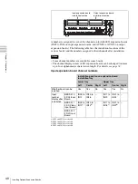
I/O expansion slot (lower)
In one slot you can install two input expansion boards (first
and second boards) and one output expansion board (first
board).
For details, see “Installing I/O Expansion Boards” (page
39).
2
Standard I/O module
a
SDI IN (SDI input) 1 to 8 connectors (BNC type)
Input SDI signals from video cameras and VTRs (players).
Internal frame synchronizers are provided, allowing input
of non-synchronized video signals.
b
SDI OUT (SDI output) connectors (BNC type)
Output SDI signals. There are four SDI output connectors:
PGM1, PGM2, AUX1, and AUX2.
PGM1, 2 (program 1, 2) connectors:
Connect to the SDI
input connectors of monitors or other devices. These
connectors output the signals processed by this unit
(program signals). The PGM1 and PGM2 connectors
output the same signals.
AUX1, 2 (auxiliary 1, 2) connectors:
Connect to the SDI
input connectors of monitors or other devices. These
connectors can output the same signals as the PGM1,
2 connectors. They can also output other types of
signals, including output preview (PVW) signals,
clean (CLN) signals, key output (KeyOut) signals,
multi-view (MV) signals, and the input signals of this
unit (In01 to In24). You can specify output of different
signals from the AUX1 connector and the AUX2
connector.
Input signals In09 to In24 appear only when optional input
expansion boards have been installed.
3
External device interface connectors
a
REF IN (reference sync signal input) connectors
(BNC type)
Input an external reference sync signal. One of the
connectors can be used as a loop-through output
connector. If you will not be using loop-through output,
terminate the connector with a 75
Ω
terminator.
b
REF OUT (reference sync signal output)
connectors (BNC type)
If you are not using an external reference sync signal to the
REF IN connector, this connector outputs the internal sync
signal used by the switcher as the reference signal.
2
SDI OUT connectors
1
SDI IN 1 to 8 connectors
Note
2
REF OUT connectors
1
REF IN connectors
3
REMOTE 1, 2,
3 connectors
4
EDITOR connector
5
PANEL connector
6
GPI IN connector
7
TALLY/GPI OUT connector
Summary of Contents for DFS-900M
Page 189: ...189 Pattern List Appendix Pattern List Wipe Basic wipe ...
Page 190: ...190 Pattern List Appendix User wipe ...
Page 191: ...191 Pattern List Appendix Mask ...
Page 193: ...193 Pattern List Appendix ...
Page 194: ...194 Pattern List Appendix 3D DME effects ...
Page 195: ...195 Pattern List Appendix ...
Page 196: ...196 Pattern List Appendix User effects ...
Page 216: ...216 External Dimensions Appendix BKDF 902 1 5M E Control Panel Unit mm inches ...
Page 217: ...217 External Dimensions Appendix DFS 900M Processor Unit Unit mm inches ...


