44
Installing Optional Expansion Boards
Ch
apt
er 3 Prep
ar
at
ion
s
5
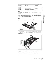
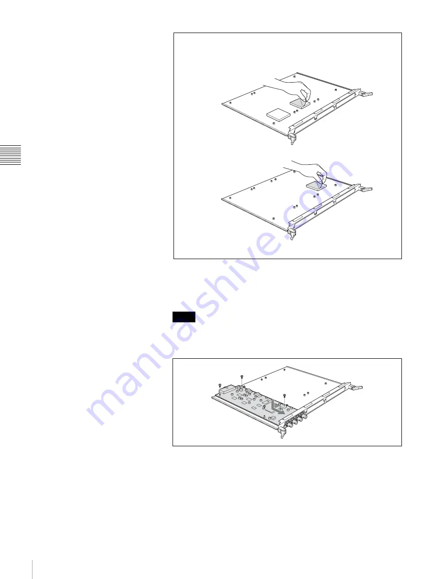
Push the connectors of the expansion board through the inner side of the
connector name plate frame, place the expansion board on the expansion
board installation tray, and secure the board with the supplied four +M3
screws.
• Use a torque screwdriver to tighten the screws. Set the tightening torque
to 0.59 N·m.
• For the installation positions of expansion boards,
6
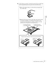
Use the following procedure to attach the connector name plate supplied
with the expansion board.
1
Using the screws (see the following table) supplied with the expansion
board, secure the connector name plate to the expansion board.
Notes
(For input expansion boards)
(For output expansion boards)
3
Remove the adhesive surface cover sheet from the top side of the
heat transfer sheet.
Summary of Contents for DFS-900M
Page 189: ...189 Pattern List Appendix Pattern List Wipe Basic wipe ...
Page 190: ...190 Pattern List Appendix User wipe ...
Page 191: ...191 Pattern List Appendix Mask ...
Page 193: ...193 Pattern List Appendix ...
Page 194: ...194 Pattern List Appendix 3D DME effects ...
Page 195: ...195 Pattern List Appendix ...
Page 196: ...196 Pattern List Appendix User effects ...
Page 216: ...216 External Dimensions Appendix BKDF 902 1 5M E Control Panel Unit mm inches ...
Page 217: ...217 External Dimensions Appendix DFS 900M Processor Unit Unit mm inches ...


