59
Connecting Up the Switcher
Chapt
er
3
Pre
par
at
ion
s
1
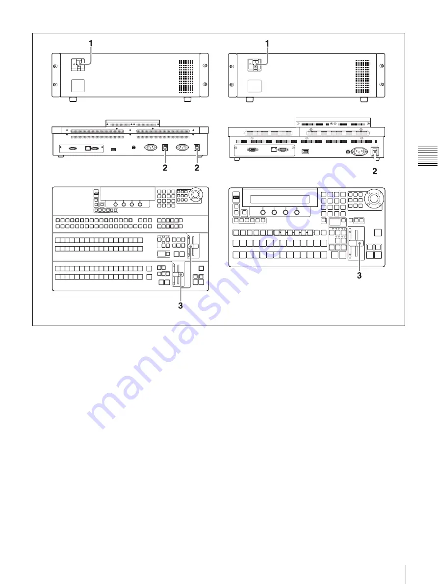
Turn on the POWER switch on the processor unit by pressing the
@
of the
switch.
The processor unit is powered on, and the POWER indicator lights in green.
2
Turn on the POWER switch (when using the BKDF-901) or the POWER
switches A and B (when using the BKDF-902) on the rear panel of the
control panel.
The control panel is powered on, and the panel buttons and display panel
light.
The control panel enters boot mode after the power is turned on. Several
minutes are required before the control panel can be operated.
When the control panel exits boot mode, the following information appears
in the display panel.
BKDF-902
BKDF-901
Summary of Contents for DFS-900M
Page 189: ...189 Pattern List Appendix Pattern List Wipe Basic wipe ...
Page 190: ...190 Pattern List Appendix User wipe ...
Page 191: ...191 Pattern List Appendix Mask ...
Page 193: ...193 Pattern List Appendix ...
Page 194: ...194 Pattern List Appendix 3D DME effects ...
Page 195: ...195 Pattern List Appendix ...
Page 196: ...196 Pattern List Appendix User effects ...
Page 216: ...216 External Dimensions Appendix BKDF 902 1 5M E Control Panel Unit mm inches ...
Page 217: ...217 External Dimensions Appendix DFS 900M Processor Unit Unit mm inches ...

