15
BKDF-901 1M/E Control Panel
Cha
pt
er 2
Name
s an
d F
unc
tions
of
P
ar
ts
Second press:
With DME still enabled, use a
key-processed signal as the key.
r
Third press:
The button goes out, and DME is disabled
again.
3
KEY DELEGATION Block
This block allows you to select KEY1 to KEY4, DSK1, or
DSK2 as the target of key, mask, and other operations.
When you press one of the buttons in this block, it selects
the corresponding key as the operation target.
The pressed button lights in green and all of the other
buttons go out.
If you press a button while it is lit in green, all of the
buttons go out and key is not selected as the operation
target.
The selection made here specifies the target of operations
with buttons in the following blocks.
• KEYER block
• DME settings buttons and USER button in the DME/
SETUP block.
• AUTO CK, WIPE POS, DME POS, and DME ROT
buttons in the joystick block.
Selections made with these buttons are linked to menu
operations. Operations with the buttons may cause a menu
to appear, and operations in the menu may cause the
buttons to light or go out.
4
Cross-Point Bus Block
This block allows you to select material signals to use in
creating the video.
a
PROGRAM selection button row
These buttons select current on-air background video.
For the functions of the various buttons, see “Assigning
video input signals to cross-point selection buttons” (page
76).
b
PRESET selection button row
These buttons select the video that will be the on-air
background after a transition.
The signals that are assigned to the buttons in this row are
the same as the signals that are assigned to the buttons in
the PROGRAM selection button row.
About the SHIFT buttons
The SHIFT buttons on the right side of the PROGRAM
and PRESET selection button rows allow you to switch
between the two signals assigned to each button in the
rows.
The SHIFT buttons have two operating modes: one in
which the buttons function as shift buttons only while held
down, and one in which the shift function is alternately
enabled and disabled each time the buttons are pressed.
For details, see “Selecting the operating mode of the
SHIFT buttons” (page 105).
5
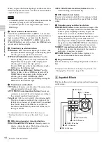
Transition Block
This block allows you to set up and execute transitions.
a
TRANS PVW (transition preview) button
Allows you to check the video of a transition before
carrying out the transition.
1
PROGRAM selection button row
2
PRESET selection button row
6
FTB button
1
TRANS PVW button
8
Key priorities block
7
Transition range and direction
buttons
4
Transition execution block
3
Transition type selection buttons
2
Next transition selection buttons
5
DSK transition buttons
Summary of Contents for DFS-900M
Page 189: ...189 Pattern List Appendix Pattern List Wipe Basic wipe ...
Page 190: ...190 Pattern List Appendix User wipe ...
Page 191: ...191 Pattern List Appendix Mask ...
Page 193: ...193 Pattern List Appendix ...
Page 194: ...194 Pattern List Appendix 3D DME effects ...
Page 195: ...195 Pattern List Appendix ...
Page 196: ...196 Pattern List Appendix User effects ...
Page 216: ...216 External Dimensions Appendix BKDF 902 1 5M E Control Panel Unit mm inches ...
Page 217: ...217 External Dimensions Appendix DFS 900M Processor Unit Unit mm inches ...


