background image

 2004 Sony Corporation

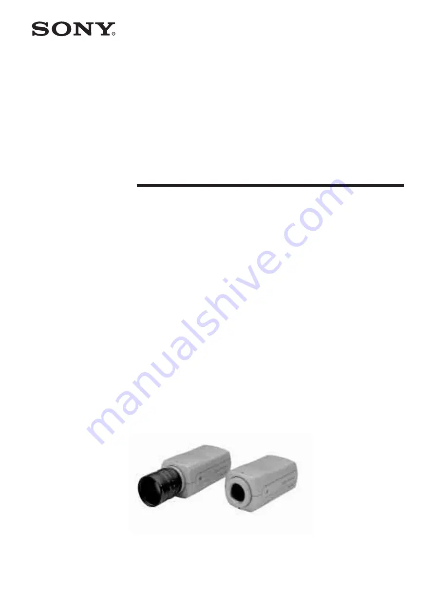
Color Digital Camera

A-BVP-100-

11 

(1)

Technical Manual

DFW-SX910/X710

Summary of Contents for DFW-SX910

Page 1: ... 2004 Sony Corporation Color Digital Camera A BVP 100 11 1 Technical Manual DFW SX910 X710 ...

Page 2: ...4 Exposure Out 14 Control Camera Command Status Register 15 Memory Map 15 ConfigROM 16 Control Base Address 18 Verifying Supported Video Modes 18 Video Mode Settings 20 Starting StoppingVideoTransfer Continuous Shot 20 One Shot and Multi Shot 20 Memory Channel Operation 21 Feature Controls Complies with the IIDC Standard 22 Feature Controls IIDC Extended 27 PAINT Control 28 Memory Shot Control 28 ...

Page 3: ...disconnected while the unit is turned on and no terminators and no ID settings such as those necessary for the SCSI interface are required The Institute of Electrical and Electronics Engineers Inc Main Features The DFW SX910 video camera module utilizes a 1 2 type PS IT CCD and the DFW X710 utilizes a 1 3 type PS IT CCD High speed digital interface IEEE1394 The transmission speed is 400 Mbps The D...

Page 4: ...put image format You can select and output any rectangle part from a full size image This allows you to efficiently capture images at a faster frame rate C mount Non compressed YUV4 1 1 YUV4 2 2 Mono8 8 bits each Solid aluminum diecast chassis ...

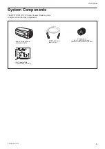
Page 5: ...ts The DFW SX910 X710 Video Camera Module system comprises the following components Video Camera Module DFW SX910 X710 IEEE1394 Cable 6 pin 4 5 m C mount Lens J6 11 MACRO Canon 25MM HD LENS VF2509 Canon Host Adapter Card Commercially available ...

Page 6: ...6 Overview DFW SX910 X710 Connection Diagram C mount Lens Recommended Lens J6 11 MACRO Canon 25MM HD LENS VF2509 Canon DFW SX910 X710 IEEE1394 Cable Host Adapter Card Host Equipment PC etc ...

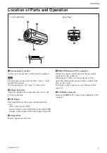
Page 7: ... operation states OFF Camera power OFF Green Camera power ON Video signal output OFF Orange Camera power ON Video signal output ON 4 Tripod hole Install a tripod into this hole Rear Panel Front Top Bottom 1 2 5 TRIG IN Exposure OUT connector Connect the trigger signal generator trigger output connector to this connector When trigger is OFF or software trigger is ON a signal that indicates the expo...

Page 8: ...ance and One Push White Balance In the Auto White Balance mode the camera senses any change in lighting and automatically adjusts White Balance accordingly In the One Push White Balance mode the White Balance is adjusted automatically once and fixed until you perform the adjustment again The camera s internal circuits integrate the image data within a defined area using an algorithm that approxima...

Page 9: ...3 P 1000 P2 E 0 000005 1000000 P 1000 P 1150 E P 1000 0 1 1 000005 Input Output Gamma ON 2 Gamma ON 1 Gamma OFF Setting examples 3 003h 14 µs 1 100000 32 020h 1 005 ms 1 1000 100 064h 10 005 ms 1 100 1000 3E8h 1 s 1010 3F2h 2 s 1150 47Eh 16 s For details on Auto Exposure see page 8 For long exposure times When exposure times longer than the currently set frame rate cycle are set the camera enters ...

Page 10: ...e Trigger or via a command sent from application software Software Trigger There are two trigger modes Trigger Mode 0 where the exposure time is controlled by the shutter parameter Trigger Mode 1 where the exposure time is controlled by the trigger pulse width In both modes the leading edge of the hardware trigger starts the exposure In Trigger Mode 0 the maximum exposure is limited by the shutter...

Page 11: ...ing information and retains it even if the power is turned off Therefore the camera loads the information from that channel when the power is turned on The video mode settings are loaded only when the power is turned on To start up the camera with the desired setting perform the following procedure 1 Make changes to the camera features or the video mode settings 2 Store the current setting in Memo...

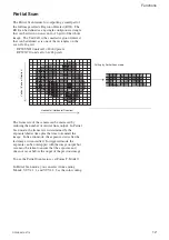
Page 12: ...DFW SX910 unit cell 80 60 pixels DFW X710 unit cell 64 48 pixels The frame rate of the camera can be increased by reducing the number of vertical lines output In Partial Scan mode the frame rate is determined by the exposure shutter time plus the time to transmit the image In free run mode the exposure starts after the last image is transmitted In triggered mode the exposure can be overlapped with...

Page 13: ...gurations This is especially useful in hardware triggered environments Multiple cameras can be setup to acquire one or more images simultaneously without consuming any 1394 bus bandwidth The applications software can setup the multiple cameras on a single 1394 bus on one computer for Memory Shot acquisition query the camera to verify that the image s are in the camera on board memory and tell each...

Page 14: ...ilable 32 MBytes sec and ISO channels 4 8 depending on your computer 1394 interface Bandwidth is allocated based on the resolution and frame rate selected for the camera To reduce the bandwidth for a camera reduce the output image size and or the frame rate For instance if a camera is to transmit 1280 960 in YUV4 2 2 at 7 5 fps approximately 18 4 MBytes sec more than half the available bandwidth R...

Page 15: ...number of bits that can be allocated to the camera as address space is 24 bits The bus and node IDs may be changed if the topology is restructured because of bus reset so only the least significant 32 address bits are shown in this Technical Manual Address Register F0000000 Base address F0000400 ConfigROM area F0F00000 Base addresses for camera commands F0F00000 CameraInitialize F0F00100 Video For...

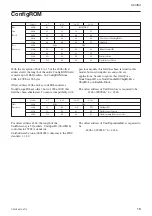
Page 16: ...rectory is required to be 424h 000004h 4 434h For offset address 434h the length of the UnitDirectory is 3 Quadlets UnitSpecID 00A02Dh conforms to 1394TA standards UnitSoftwareVersion 000102h conforms to the IIDC standard v 1 30 The offset address of UnitDependentInfo is required to be 440h 000001h 4 444h Offset 0 7 8 15 16 23 24 31 Bus 400h 04 1F ROM CRC Info 404h 31 33 39 34 Block 408h 20 FF 60 ...

Page 17: ...For the DFW X710 the15 characters are DFW X710 v1 02A Model names are subject to change with the upgrade of firmware Offset 0 7 8 15 16 23 24 31 Unit 444h 0003 CRC Dependent 448h 40 3C 00 00 CommandRegsBase Info 44ch 81 00 00 02 VendorNameLeaf 450h 82 00 00 05 ModelNameLeaf VendorNameLeaf Offset 0 7 8 15 16 23 24 31 Vendor 454h 0003 CRC Name 448h 00 00 00 00 Leaf 44ch 00 00 00 00 450h 53 4F 4E 59 ...

Page 18: ...amera Verifying Supported Video Modes First we will find out what video formats are supported Data Address DFW SX910 DFW X710 F0F00100h E1000000h C1000000h We find that the DFW SX910 supports Format0 1 2 7 and the DFW X710 supports Format0 1 7 Next for each format we will find out which video modes are supported Format0 Data Address DFW SX910 DFW X710 F0F00180h 74000000h 74000000h We find video mo...

Page 19: ... 640 480 Mono8 a a 1 0 800 600 YUV4 2 2 a a 2 800 600 Mono8 a 3 1024 768 YUV4 2 2 a a a 5 1024 768 Mono8 a a a 2 0 1280 960 YUV4 2 2 a a a 2 1280 960 Mono8 a a a Frame Rate Format Mode Image Size Color Coding 15 7 5 3 75 1 875 0 1 320 240 YUV4 2 2 a a a 2 640 480 YUV4 1 1 a a a 3 640 480 YUV4 2 2 a a a 5 640 480 Mono8 a a a 1 0 800 600 YUV4 2 2 a a a 2 800 600 Mono8 a a 3 1024 768 YUV4 2 2 a a a a...

Page 20: ... after the preparations for receiving isochronous data are made video transfer starts when the following commands are issued Address Data F0F00614h 80000000h When the following command is issued video transfer stops Address Data F0F00614h 00000000h One Shot and Multi Shot This camera supports both One Shot and Multi Shot commands With a One Shot command after outputting just one single frame image...

Page 21: ...ion in Ch 2 The settings of the camera features and the video mode can be stored The camera memorizes the channel most recently used to read out the setting information using nonvolatile memory Then the information in that channel will be loaded when the power is turned on the next time The video mode settings are loaded only when the power is turned on If you read out Memory Channels during opera...

Page 22: ...e time To control this feature you can use both relative control values from 1 100 000 of a second to 16 seconds allocated from 3 to 1150 and absolute value control with values from 1 100 000 of a second to 17 5 seconds set continuously Gain Controls the gain in the range from 0 dB to 18 dB The unit of the adjustment is approximately 0 035 dB Trigger Controls external triggers This feature support...

Page 23: ... Sharpness 4 The value can be read out 7 Manual setting can be selected 8 19 Min 0 20 31 Max 7 F0F0050Ch 9B700900h 0 This feature exists White Balance 3 One Push Auto mode can be selected 4 The value can be read out 6 Auto setting can be selected 7 Manual setting can be selected 8 19 Min 1792 20 31 Max 2304 F0F00510h 890530ADh 0 This feature exists Hue 4 The value can be read out 7 Manual setting ...

Page 24: ...rce0 exists 2 15 Software Trigger Mode exists 2 16 Trigger Mode0 exists 17 Trigger Mode1 exists F0F00584h 89 0 This feature exists Pan 4 The value can be read out F0F00584h 7 Manual setting can be selected Tilt 8 19 Min Depends on the video mode 20 31 Max Depends on the video mode F0F0058Ch 89000001h 0 This feature exists Optical Filter 4 The value can be read out 7 Manual setting can be selected ...

Page 25: ...ctivates the gamma feature gamma curve 1 82000082 Activates the gamma feature gamma curve 2 Shutter exposure time control Address Data F0F0081C 82000ddd Controls shutter using the manually set relative value 83000xxx Sets Shutter to AUTO C2000xxx Controls shutter using the absolute control value F0F00970 After F0F0081C has been set to Absolute value control set exposure time using this register Ga...

Page 26: ... control register address Absolute value shutter control CSR offset address Address Data F0F0071C 003C025C Absolute value shutter control CSR offset The register address for absolute value shutter control is given by the following formula F0000000h 003C025Ch 4 F0F00970h ...

Page 27: ...r to the camera is turned off To control these extended features Vendor Unique Features use the Access Control Register defined by the IIDC standard The formula for the ACR offset address First we will find out whether the camera supports Vender Unique Features F0F00400h 80001802h 0 Vender Unique Features are supported BASIC_FUNC_INQ 19 One Shot can be transmitted 20 Multi Shot can be transmitted ...

Page 28: ... video start command The camera outputs the frames in the memory area and then enters the idling state The frames are output sequentially in the captured order You cannot specify a frame to be output on a random basis 8 If output ends issue the video stop command This step cannot be skipped One procedure is completed You can perform the operation from step 4 over again To exit from the Memory Shot...

Page 29: ...d with color coding set to YUV4 2 2 the packet size set to maximum in order to capture the image at the highest speed Start Set the format Check available modes Set the mode Obtain a CSR offset address Go to Step 2 Write E0000000h in F0F00608h Set the format to 7 Read F0F0019Ch C0000000h is returned showing Mode0 and Mode1 are available Write 00000000h in F0F00604h Set the Mode to 0 Read F0F002E0h...

Page 30: ...ize is 80 60 Therefore the screen can be divided into 256 sections 16 16 vertically and horizontally Read F0F10014h E0000000h is returned showing Mono8 YUV4 1 1 and YUV4 2 2 are available Write 018000F0h in F0F10008h Horizontal position 320 Vertical position 240 Write 028001E0h in F0F1000Ch Width 640 Height 480 Write 02000000h in F0F10010h YUV4 2 2 2 Write C0000000h in F0F1007Ch Read F0F1007Ch Wai...

Page 31: ... of the effective image is obtained Image transmission is now ready Send a video start command to output images The camera does not support RecBytePerPacket Read F0F10040h Packet size that can be set is obtained 640 minimum and 1280 maximum for this camera Write 02800000h in F0F10044h PacketSize 1280 Read F0F1007Ch Check that Bit 9 is not set If an error occurs the PacketSize was wrong Try other s...

Page 32: ...an occur and it cannot capture the correct image Make sure that the following conditions are met when the trigger is activated Appendix However partial activation can be used if the following conditions are exceeded Refer to the table on pages 37 and 38 T T 3 When AE Auto Exposure is not available The camera loads the AE function that controls Gain and Shutter automatically However the function wo...

Page 33: ...ble for the features Following the process listed below is recommended for setting the isochronous control register Set the isochronous channel isochronous speed F0F0060Ch Set the video format F0F00608h Set the video mode F0F00604h Set the frame rate F0F00600h Confirm the variable range for the various features F0F00500 F0F005FCh Set the features as needed F0F00800 F0F008FCh Prepare for video data...

Page 34: ...y output after the A period from the falling edge of the VD The following figure shows an example where the frame rate is 7 5 fps for the DFW SX910 and 15 fps for the DFW X710 DFW SX910 7 5 fps A Approx 1 ms or less DFW X710 15fps A Approx 1 ms or less The timing when the Trigger Mode is set to 1 is the same as above In this case the exposure time is defined by the Trigger pulse width Approx 120 m...

Page 35: ...UV 4 2 2 4 1 1 Mono8 DFW X710 1024 768 YUV 4 2 2 4 1 1 Mono8 Partial scan function 16 16 256 sections Lens mount C mount Flange back 17 526 mm Minimum illumination 20 lx F0 95 Gain 18 dB White balance One Push ATW preset 3200 K 5600 K manual Hue Adjustable Saturation Adjustable Brightness Adjustable Gamma Variable CCD Iris ON OFF Shutter 1 100 000 to 17 5 s Absolute value control possible Gain Aut...

Page 36: ... 7 0 1024 768 Mono8 a 16 16 Not specified 0 1024 768 YUV4 1 1 a 16 16 Not specified 1 1024 768 YUV4 2 2 a 16 16 Not specified Frame Rate Format Mode Image Size Color Coding 15 7 5 3 75 1 875 0 1 320 240 YUV4 2 2 a a 2 640 480 YUV4 1 1 a a 3 640 480 YUV4 2 2 a a 5 640 480 Mono8 a a 1 0 800 600 YUV4 2 2 a a 2 800 600 Mono8 a 3 1024 768 YUV4 2 2 a a a 5 1024 768 Mono8 a a a 2 0 1280 960 YUV4 2 2 a a ...

Page 37: ...ps 1024 48 49 0 20 4 16 0 62 5 1024 96 52 1 19 2 19 0 52 6 1024 144 54 9 18 2 22 0 45 5 1024 192 58 8 17 0 26 0 38 5 1024 240 62 1 16 1 29 0 34 5 1024 288 64 9 15 4 31 9 31 3 1024 336 69 0 14 5 36 0 27 8 1024 384 71 9 13 9 39 1 25 6 1024 432 75 2 13 3 42 0 23 8 1024 480 78 7 12 7 46 1 21 7 1024 528 82 0 12 2 49 0 20 4 1024 576 84 7 11 8 52 1 19 2 1024 624 89 3 11 2 54 9 18 2 1024 672 91 7 10 9 58 ...

Page 38: ...time ms Frame rate fps 1280 60 65 8 15 2 34 0 29 4 1280 120 71 9 13 9 39 1 25 6 1280 180 78 1 12 8 45 0 22 2 1280 240 84 0 11 9 50 0 20 0 1280 300 89 3 11 2 55 9 17 9 1280 360 95 2 10 5 62 1 16 1 1280 420 100 0 10 0 67 1 14 9 1280 480 106 4 9 4 73 0 13 7 1280 540 112 4 8 9 78 7 12 7 1280 600 116 3 8 6 84 0 11 9 1280 660 123 5 8 1 90 1 11 1 1280 720 128 2 7 8 96 2 10 4 1280 780 133 3 7 5 101 0 9 9 ...

Page 39: ...s 1280 H 960 V Max Size of unit cell 4 65 µm H 4 65 µm V DFW X710 Total number of pixels 1077 H 788 V Number of effective pixels 1034 H 779 V Number of output pixels 1024 H 768 V Size of unit cell 4 65 µm H 4 65 µm V V 960 1280 1040 40 56 2 1392 40 8 2 Output pixel area Effective pixel area Output pixel area Effective pixel area V 768 1024 779 6 5 3 1034 40 7 2 H H ...

Page 40: ...Appendix DFW SX910 X710 Spectral Sensitivity Relative Response Parameters Without lens and light source parameters DFW SX910 X710 Relative Response 0 0 2 0 4 0 6 0 8 1 Wave Length nm 400 500 600 700 R G B ...

Page 41: ...41 Appendix DFW SX910 X710 Dimensions Unit mm 55 25 5 50 5 3 5 33 4 16 55 56 13 25 41 110 1 4 20UNC 4 M3 Effective Depth 5 1 32UNC 1 ...

Reviews: