5-58
1010=A
1111=F
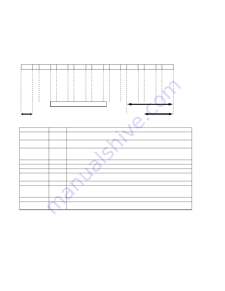
←
UNLOAD
Releasing lock of
cassette compartment
LS chassis movement range
Pinch roller is pressed
Tension regulator ON
EJECT
BL
1110=E
1111=F
USE
BL
1100=C
1111=F
SOFF
BL
1101=D
1111=F
DS
BL
1001=9
1111=F
LE
BL
0101=5
1111=F
STOP
BL
0111=7
1111=F
FF
BL
1011=B
0011=3
1111=F
RP
RVS
BL
LOAD
→
Mechanism Position
Position
EJECT
BL
USE
SOFF
DS
LE
STOP
FF
RP
RVS
NULL
Code
A
F
E
C
D
9
5
7
B
3
0
Contents
Position at which the cassette compartment lock is released, and position at the farthest unload side
mechanically at which the mechanism can move no further in the UNLOAD direction.
BLANK code, at the boundary between codes. The mechanism will not stop at this code during
operations. (Excluding LOAD/UNLOAD)
EJECT completion position. When the cassette is ejected, the mechanism will stop at this position.
Cassette IN standby. The guide will start protruding out as the mechanism moves towards the
LOAD position.
Code during loading. Code outputs while the LS chassis is moving.
LS operations and guide loading are performed here.
Current limiter is turned off.
Stop position in the loading state. The pinch roller separates, the tension regulator returns, and the
brake is imposed on both reels.
FF position. The tension regulator is half on. This position is not used except for the FF mode.
PB, REC, CUE, Pause, FX2, FWD-SLOW positions. When the pinch roller is pressed, and the
tension regulator is ON, the mechanism is operating at this position in modes in which normal
images are shown.
Reverse running position. REW, REV, RX1, RX2, and RVS-SLOW are performed at this position.
Code not existing in the MD. When errors occur when the loading motor is not driving, this code is
memorized.
2-2. MSW Code
MSW when errors occur:
Information on MSW (mode SW) when errors occur
MSW when movement starts:
Information on MSW when movements starts when the mechanism position is moved (When the L motor is moved)
MSW of target of movement:
Information on target MSW of movement when the mechanism position is moved
Summary of Contents for Digital Handycam DCR-TRV10
Page 10: ...1 2 ...
Page 11: ...1 3 ...
Page 12: ...1 4 ...
Page 13: ...1 5 ...
Page 14: ...1 6 ...
Page 15: ...1 7 ...
Page 16: ...1 8 ...
Page 17: ...1 9 ...
Page 18: ...1 10 ...
Page 19: ...1 11 ...
Page 20: ...1 12 ...
Page 21: ...1 13 ...
Page 22: ...1 14 ...
Page 23: ...1 15 ...
Page 24: ...1 16 ...
Page 25: ...1 17 ...
Page 26: ...1 18 ...
Page 27: ...1 19 ...
Page 28: ...1 20 ...
Page 29: ...1 21 ...
Page 30: ...1 22 ...
Page 31: ...1 23 ...
Page 32: ...1 24 ...
Page 33: ...1 25 ...
Page 34: ...1 26 ...
Page 35: ...1 27 ...
Page 36: ...1 28 ...
Page 37: ...1 29 ...
Page 38: ...1 30 ...
Page 39: ...1 31 ...
Page 40: ...1 32 ...
Page 41: ...1 33 ...
Page 42: ...1 34 ...
Page 43: ...1 35 ...
Page 44: ...1 36 ...
Page 45: ...1 37E ...
Page 57: ...DCR TRV8 TRV8E TRV10 TRV10E 3 5 3 6 3 7 3 8 3 2 OVERALL BLOCK DIAGRAM TRV10 TRV10E ...
Page 58: ...DCR TRV8 TRV8E TRV10 TRV10E 3 3 POWER BLOCK DIAGRAM 3 9 3 10 3 11 3 12E ...
Page 180: ... 264 OPTICAL AXIS FRAME Take a copy of OPTICAL AXIS FRAME with a clear sheet for use ...


