background image

– 31 –

NOTE :

• Due to standardization, replacements in the

parts list may be different from the parts
specified in the diagrams or the components
used on the set.

• -XX,  -X mean standardized parts, so they

may have some difference from the original
one.

• RESISTORS

All resistors are in ohms
METAL : Metal-film resistor
METAL OXIDE :Metal oxide-film resistor
F : nonflammable

• Items marked “ * ”are not stocked since

they are seldom required for routine service.
Some delay should be anticipated when
ordering these items.

• SEMICONDUCTORS

In each case, u : 

µ

, for example :

uA.... : 

µ

A.... , uPA.... : 

µ

PA....

uPB.... : 

µ

PB.... , uPC.... : 

µ

PC....

uPD.... : 

µ

PD....

• CAPACITORS

uF : 

µ

F

• COILS

uH : 

µ

H

• Abbreviation

AR

: Argentine

G

: German

AUS

: Australian

CND : Canadian

FR

: French

HK

: Hong Kong

EA

: Saudi Arabia

CN

: Chinese

EE

: East European

AEP

: Manual of English is attached

7AEP : Manual of 9 language is attached
C&SA : Central and South America
E13

: AC220-230V area model

E33

: AC100-240V area model

Les composants identifiés par une
marque 

!

 sont critiques pour la sécurité.

Ne les remplacer que par une pièce
portant le numéro spécifié.

When indicating parts by reference num-
ber, please include the board.

The components identified by mark 

!

or dotted line with mark 

!

 are critical

for safety.
Replace only with part number specified.

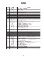
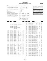
SECTION 8

ELECTRICAL PARTS LIST

Ref. No.

Part No.

Description

Remark

Ref. No.

Part No.

Description

Remark

MAIN

A-3323-101-A MAIN BOARD,COMPLETE (FR)

*********************

A-3323-102-A MAIN BOARD,COMPLETE (EXCEPT FR)

********************

4-213-876-01 HOLDER(LCD)
4-978-695-01 PLATE,TERMINAL, BATTERY

< CAPACITOR >

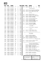
C101

1-126-794-11 ELECT

4.7uF

20%

50V

C102

1-164-360-11 CERAMIC CHIP

0.1uF

16V

C103

1-115-156-11 CERAMIC CHIP

1uF

10V

C104

1-162-953-11 CERAMIC CHIP

100PF

5%

50V

C105

1-162-953-11 CERAMIC CHIP

100PF

5%

50V

C106

1-162-927-11 CERAMIC CHIP

100PF

5%

50V

C108

1-162-968-11 CERAMIC CHIP

0.0047uF 10%

50V

C201

1-126-794-11 ELECT

4.7uF

20%

50V

C202

1-164-360-11 CERAMIC CHIP

0.1uF

16V

C203

1-115-156-11 CERAMIC CHIP

1uF

10V

C204

1-162-953-11 CERAMIC CHIP

100PF

5%

50V

C205

1-162-953-11 CERAMIC CHIP

100PF

5%

50V

C206

1-162-927-11 CERAMIC CHIP

100PF

5%

50V

C208

1-162-968-11 CERAMIC CHIP

0.0047uF 10%

50V

C302

1-164-360-11 CERAMIC CHIP

0.1uF

16V

C303

1-164-360-11 CERAMIC CHIP

0.1uF

16V

C304

1-124-635-00 ELECT

220uF

20%

6.3V

C305

1-124-584-00 ELECT

100uF

20%

10V

C306

1-162-968-11 CERAMIC CHIP

0.0047uF 10%

50V

C307

1-126-795-11 ELECT

10uF

20%

25V

C308

1-126-795-11 ELECT

10uF

20%

25V

C312

1-128-057-11 ELECT

330uF

20%

6.3V

C313

1-164-505-11 CERAMIC CHIP

2.2uF

16V

C314

1-115-156-11 CERAMIC CHIP

1uF

10V

C315

1-126-514-11 ELECT

22uF

20%

10V

C316

1-216-864-11 METAL CHIP

0

5%

1/16W

C317

1-115-156-11 CERAMIC CHIP

1uF

10V

C323

1-164-360-11 CERAMIC CHIP

0.1uF

16V

C324

1-162-953-11 CERAMIC CHIP

100PF

5%

50V

C326

1-115-467-11 CERAMIC CHIP

0.22uF

10%

10V

C335

1-162-919-11 CERAMIC CHIP

22PF

5%

50V

C401

1-162-970-11 CERAMIC CHIP

0.01uF

10%

25V

C402

1-126-785-11 ELECT

47uF

20%

10V

C403

1-127-485-00 ELECT

33uF

20%

6.3V

C404

1-162-923-11 CERAMIC CHIP

47PF

5%

50V

C405

1-164-004-11 CERAMIC CHIP

0.1uF

10%

25V

C406

1-164-360-11 CERAMIC CHIP

0.1uF

16V

C407

1-115-156-11 CERAMIC CHIP

1uF

10V

C408

1-162-964-11 CERAMIC CHIP

0.001uF

10%

50V

C410

1-164-360-11 CERAMIC CHIP

0.1uF

16V

C411

1-164-360-11 CERAMIC CHIP

0.1uF

16V

C414

1-115-156-11 CERAMIC CHIP

1uF

10V

C415

1-135-201-11 TANTALUM CHIP 10uF

20%

4V

C417

1-104-852-11 TANTAL. CHIP

22uF

20%

6.3V

C420

1-164-360-11 CERAMIC CHIP

0.1uF

16V

C421

1-124-635-00 ELECT

220uF

20%

6.3V

C424

1-162-964-11 CERAMIC CHIP

0.001uF

10%

50V

C425

1-162-970-11 CERAMIC CHIP

0.01uF

10%

25V

C426

1-162-953-11 CERAMIC CHIP

100PF

5%

50V

C427

1-104-852-11 TANTAL. CHIP

22uF

20%

6.3V

C428

1-164-505-11 CERAMIC CHIP

2.2uF

16V

C432

1-115-156-11 CERAMIC CHIP

1uF

10V

C437

1-115-156-11 CERAMIC CHIP

1uF

10V

C439

1-162-970-11 CERAMIC CHIP

0.01uF

10%

25V

C501

1-162-919-11 CERAMIC CHIP

22PF

5%

50V

C503

1-162-970-11 CERAMIC CHIP

0.01uF

10%

25V

C504

1-162-962-11 CERAMIC CHIP

470PF

10%

50V

C505

1-162-967-11 CERAMIC CHIP

0.0033uF 10%

50V

C506

1-164-506-11 CERAMIC CHIP

4.7uF

16V

C509

1-164-360-11 CERAMIC CHIP

0.1uF

16V

C510

1-164-360-11 CERAMIC CHIP

0.1uF

16V

C511

1-164-360-11 CERAMIC CHIP

0.1uF

16V

C512

1-115-156-11 CERAMIC CHIP

1uF

10V

C513

1-165-176-11 CERAMIC CHIP

0.047uF

10%

16V

C514

1-162-953-11 CERAMIC CHIP

100PF

5%

50V

C515

1-162-962-11 CERAMIC CHIP

470PF

10%

50V

C516

1-164-360-11 CERAMIC CHIP

0.1uF

16V

C517

1-109-982-11 CERAMIC CHIP

1uF

10%

10V

C518

1-162-966-11 CERAMIC CHIP

0.0022uF 10%

50V

C519

1-162-964-11 CERAMIC CHIP

0.001uF

10%

50V

Summary of Contents for Discman D-E440

Page 1: ...ck Output level 0 7 V rms at 47 kilohms Recommended load impedance over 10 kilohms General Power requirements For the area code of the model you purchased check the upper left side of the bar code on the package Sony BP DM10 Rechargeable battery 2 4 V DC Ni Cd 650 mAh Sony BP DM20 Rechargeable battery 2 4 V DC Ni MH 1 200 mAh Two LR6 size AA batteries 3 V DC AC power adaptor DC IN 4 5 V jack US Ca...

Page 2: ...conductor when soldering or unsoldering Notes on chip component replacement Never reuse a disconnected chip component Notice that the minus side of a tantalum capacitor may be damaged by heat TABLE OF CONTENTS This Compact Disc player is classified as a CLASS 1 LASER product The CLASS 1 LASER PRODUCT label is located on the bottom exterior CAUTION Use of controls or adjustments or performance of p...

Page 3: ...n you check the emission of laser diode Laser Diode Checking Methods During normal operation of the equipment emission of the laser diode is prohibited unless the upper panel is closed while turning ON the S801 push switch type The following two checking methods for the laser diode are operable Method 1 In the service mode or normal operation Emission of the laser diode is visually checked 1 Open ...

Page 4: ...S switch VOLUME control Sound switch FR button Information display panel REPEAT ENTER button HOLD switch 1 234 5 7 8 9 0 6 p HOLD VOL volume Remote control Earphones AMS search play AMS search p stop Automatic Music Sensor When you are not using the remote control slide HOLD in the direction of the arrow to prevent any accidental operation To unlock slide HOLD back Note Use only the supplied remot...

Page 5: ...SSY CABINET REAR ASSY MD ASSY Lid ASSY Upper Cabinet Front ASSY Cabinet Rear ASSY MD ASSY Set Main board Lid ASSY Upper 2 1 OPEN 1 Screws 1 4x2 5 1 Screw 1 4x2 5 º CN501 4 Claw 4 Claw Claw 8 CN702 7 CN701 9 CN703 6 5 3 MD ASSY Cabinet Front ASSY Cabinet Rear ASSY 2 OPEN r The equipment can be removed using the following procedure ...

Page 6: ...MAIN BOARD 1 Main board S804 S804 Knob HOLD Knob RESUME Cabinet Rear ASSY S803 S803 To install position the knob and the switch respectively Sometime the HOLD switch S804 and RESUME switch S803 will be broken ...

Page 7: ... if LCD indication is effected 2 By pressing the or key the optical pick up movable inwardly or outwardly However if this is activated tracking servo and sled servo are turned OFF so it can be turned ON by pressing the PLAY MODE key if required 3 By pressing the REPEAT ENTER key the tracking gain up mode becomes active 4 By pressing the key focus is turned ON from focus search ing while entering C...

Page 8: ...ipment to service mode After the completion of adjustment be sure to reset the service mode For more information see Service Mode service program on page 7 2 Perform adjustments in the order given 3 Use the disc YEDS 18 Part No 3 702 101 01 unless other wise indicated 4 Power supply voltage requirement DC 4 5 V HOLD switch OFF VOLUME Minimum SOUND switch NORM AVLS switch OFF Before Beginning Adjus...

Page 9: ...E DIV 5mS Waveform when tracking gain lowered Fundamental wave appears large waves Fig 1 Waveform when fundamental wave disappears no large waves Fig 2 Waveform when no traverse waveform during 100 track jump Brake application is smooth because of adjustment Fig 3 Waveform when no traverse waveform during 100 track jump Brake application is poor because of adjustment Fig 4 0V 0V 0V 100 track jump ...

Page 10: ... 10 Adjustment Location MAIN BOARD Side A CN501 RV503 Focus Gain Adjustment RV502 Tracking Gain Adjustment ...

Page 11: ...rol output 25 XLT ESP O Latch signal output to ESP control IC601 26 HOLD SW I Hold switch input termianl L HOLD ON H HOLD OFF 27 XLMT MD I Limit switch input terminal L Inside Track 28 XRSM SW I RESUME switch input terminal L ON H OFF 29 WP XDC DT PWR I DC in voltage detection terminal 30 WP XOPEN SW I Door open switch input terminal L Close H Open 31 WP XPLAY SW I Play pause key input terminal 32...

Page 12: ...t terminal for main unit key 54 AD WRMT I A D input terminal for remote control key 55 AD HI DC I A D input terminal for DC IN voltage detection 56 AD BAT I Rechargeable battery dry cell detection input 57 AD CHGMNT I A D input terminal for charging voltage monitor 58 AD VCC I A D input terminal for VCC voltage monitor 59 AD DSP OFFSET I A D input terminal for DSP off set monitor 60 FP10 Not used ...

Page 13: ... 13 15 14 6 2 BLOCK DIAGRAM D E440 E441 E441SR E443 E445 E446CK E449CK Signal path J CD ...

Page 14: ...icated except for electrolytics and tantalums All resistors are in Ω and 1 4 W or less unless otherwise specified internal component Note Note The components identi Les composants identifiés fied by mark or dotted par une marque sont cri line with mark are cri tiques pour la sécurité tical for safety Ne les remplacer que par Replace only with part une piéce portant le number specified numéro spéci...

Page 15: ......

Page 16: ......

Page 17: ......

Page 18: ......

Page 19: ......

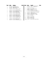
Page 20: ...1 LID ASSY UPPER ORANGE E441 5 X 4950 736 1 LID ASSY UPPER WHITE E441 5 X 4950 737 1 LID ASSY UPPER SILVER E443 5 X 4950 796 1 LID ASSY UPPER E449CK 5 X 4950 797 1 LID ASSY UPPER DARK BLUE E441 5 X 4950 798 1 LID ASSY UPPER ORANGE E445 5 X 4951 159 1 LID ASSY UPPER E441SR 6 4 213 876 01 HOLDER LCD 7 4 978 695 01 PLATE TERMINAL BATTERY 8 4 990 219 01 INSULATOR 9 A 3323 101 A MAIN BOARD COMPLETE FR ...

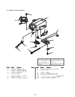
Page 21: ...S901 M902 51 52 62 53 54 55 56 57 58 59 60 61 51 A 3303 970 A SCREW ASSY FEED 52 3 318 203 11 SCREW B1 7 TAPPING 53 1 690 530 81 LEAD WITH CONNECTOR 54 4 972 163 04 SPRING SLED 55 4 974 003 01 GEAR B 56 3 719 401 11 SCREW B1 7 TAPPING 57 4 984 320 01 CHASSIS 58 1 660 965 11 PC BOARD SLIDE FLEXIBLE 59 X 4950 476 1 OPTICAL PICK UP DAX 11E RP 60 4 972 165 01 RACK 61 4 973 631 01 SCREW 62 7 627 850 17...

Page 22: ...0 1uF 16V C303 1 164 360 11 CERAMIC CHIP 0 1uF 16V C304 1 124 635 00 ELECT 220uF 20 6 3V C305 1 124 584 00 ELECT 100uF 20 10V C306 1 162 968 11 CERAMIC CHIP 0 0047uF 10 50V C307 1 126 795 11 ELECT 10uF 20 25V C308 1 126 795 11 ELECT 10uF 20 25V C312 1 128 057 11 ELECT 330uF 20 6 3V C313 1 164 505 11 CERAMIC CHIP 2 2uF 16V C314 1 115 156 11 CERAMIC CHIP 1uF 10V C315 1 126 514 11 ELECT 22uF 20 10V C...

Page 23: ... 10 50V C802 1 162 964 11 CERAMIC CHIP 0 001uF 10 50V C804 1 162 927 11 CERAMIC CHIP 100PF 5 50V C806 1 115 156 11 CERAMIC CHIP 1uF 10V C807 1 115 156 11 CERAMIC CHIP 1uF 10V C808 1 115 156 11 CERAMIC CHIP 1uF 10V C809 1 115 156 11 CERAMIC CHIP 1uF 10V C814 1 216 864 11 METAL CHIP 0 5 1 16W C879 1 115 156 11 CERAMIC CHIP 1uF 10V C907 1 164 360 11 CERAMIC CHIP 0 1uF 16V CONNECTOR CN501 1 566 530 11...

Page 24: ... 7 5 1 16W R201 1 216 813 11 METAL CHIP 220 5 1 16W R202 1 216 845 11 METAL CHIP 100K 5 1 16W R203 1 216 841 11 METAL CHIP 47K 5 1 16W EXCEPT FR R203 1 218 901 11 RES CHIP 180K 0 50 1 16W FR R205 1 216 821 11 METAL CHIP 1K 5 1 16W R207 1 216 793 11 RES CHIP 4 7 5 1 16W R304 1 216 803 11 METAL CHIP 33 5 1 16W R306 1 216 864 11 METAL CHIP 0 5 1 16W R307 1 216 821 11 METAL CHIP 1K 5 1 16W R308 1 216 ...

Page 25: ...1 METAL CHIP 6 8K 5 1 16W R821 1 216 829 11 METAL CHIP 4 7K 5 1 16W R822 1 216 827 11 METAL CHIP 3 3K 5 1 16W R823 1 216 825 11 METAL CHIP 2 2K 5 1 16W R824 1 216 823 11 METAL CHIP 1 5K 5 1 16W R825 1 216 821 11 METAL CHIP 1K 5 1 16W R826 1 216 821 11 METAL CHIP 1K 5 1 16W R829 1 216 864 11 METAL CHIP 0 5 1 16W R830 1 216 864 11 METAL CHIP 0 5 1 16W R879 1 216 857 11 METAL CHIP 1M 5 1 16W VARIABLE...

Page 26: ...440 7AEP FR E441 AEP CND FR E441SR AEP FR E443 AEP FR E445 AEP CND FR E446CK AEP CND FR 3 865 543 41 MANUAL INSTRUCTION DUTCH E440 7AEP E441 AEP EE E441SR AEP EE E443 AEP E445 AEP EE E446CK AEP EE 3 865 543 51 MANUAL INSTRUCTION SWEDISH E440 7AEP E441 AEP E441SR AEP E443 AEP E445 AEP E446CK AEP 3 865 543 61 MANUAL INSTRUCTION PORTUGUESE E440 7AEP E441 AEP AR1 C SA E441SR AEP E443 AEP E445 AEP E446...

Page 27: ... 36 D E440 441 E441SR E443 E445 E446CK E449CK 9 926 932 11 Sony Corporation Personal A V Products Company 99B0290 1 Printed in Japan 1999 2 Published by Quality Engineering Dept Shibaura ...

Reviews: