background image


Setup Menu   

6-27

Chapter 6   Setup Menu

707

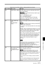
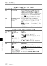
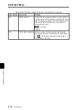
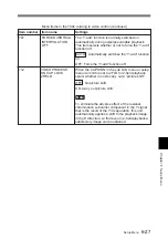
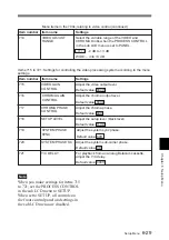
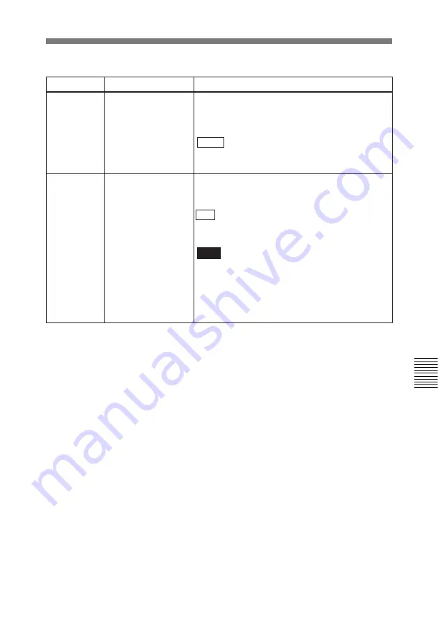
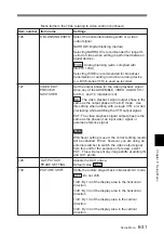
FORCED VERTICAL
INTERPOLATION
OFF

The “Y-add” function is normally switched on
automatically during noiseless variable playback.
This item selects whether or not to force the “Y-add”
function off.

 AUTO : Automatically switches the “Y-add” function
on.

OFF: Force the “Y-add” function off.

Item number

Item name

Settings

Menu items in the 700s, relating to video control (continued)

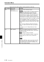
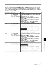
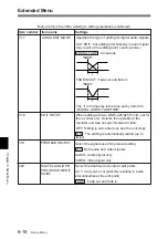
712

VIDEO PROCESS
ON CAP LOCK
2FIELD

When the CAPSTAN in the sub LCD menu or setup
menu item 106 is set to 2FLD for 2-field playback,
select whether or not to carry out a “picture shift”.

OFF : No picture shift.

ON: Carry out picture shift.

Note

To eliminate the adverse effect of the residual
chrominance subcarrier component in the Y signal
that is the result of the Y/C separation, this unit
automatically applies a shift to the playback image
in the H direction, so that even in 2-field playback a
satisfactory image can be obtained.

Summary of Contents for DNW-A25

Page 1: ...DIGITAL VIDEOCASSETTE RECORDER DNW A25 A25P OPERATION MANUAL 1st Edition Revised 4 English ...

Page 2: ...he following measures Reorient or relocate the receiving antenna Increase the separation between the equipment and receiver Connect the equipment into an outlet on a circuit different from that to which the receiver is connected Consult the dealer or an experienced radio TV technician for help You are cautioned that any changes or modifications not expressly approved in this manual could void your...

Page 3: ... 3 Handling Cassettes 2 6 2 3 1 Loading Ejecting Cassettes 2 6 2 3 2 Preventing Accidental Erasures 2 9 2 4 Setting Reference Video Signals 2 10 2 5 Setting Timecode 2 12 2 5 1 Setting an Initial Value and Recording Timecode 2 13 2 5 2 Synchronizing the Internal Timecode Generator with an External Signal 2 15 2 5 3 Synchronizing the Internal Timecode Generator with Playback Timecode Timecode Recor...

Page 4: ...earch 3 3 3 3 Setting Edit Points 3 5 3 3 1 Setting Edit Points 3 5 3 3 2 Checking Edit Points 3 6 3 3 3 Cueing Up Edit Points 3 6 3 3 4 Previewing Edit Results 3 7 3 3 5 Modifying Edit Points 3 8 3 3 6 Setting Edit Points Using the Recorder Unit Only 3 9 3 4 Executing an Edit 3 10 3 4 1 Outline of Editing Operations 3 10 3 4 2 Starting an Edit 3 11 3 4 3 Redoing an Edit 3 12 3 4 4 Displaying the ...

Page 5: ...t Mark Function Features 5 1 5 1 2 Shot Mark Operation Menu 5 2 5 1 3 Reading Shot Data 5 3 5 2 Shot Mark Operations 5 4 5 2 1 Reading Shot Marks 5 4 5 2 2 Writing Shot Marks 5 4 5 2 3 Creating a Virtual Shot Mark 5 5 5 2 4 Displaying Shot Mark List 5 5 5 2 5 Deleting Shot Marks 5 8 5 2 6 Sorting Shot Marks 5 8 5 2 7 Cueing up a Mark 5 9 Chapter 6 Setup Menu 6 1 Menu System Configuration 6 1 6 2 B...

Page 6: ...k Occurs A 1 Head Cleaning A 1 Moisture Condensation A 2 Digital Hours Meter A 3 Specifications A 5 Information Displayed on the LCD Monitor A 11 Combining Two VTRs A 16 Using the Shoulder Belt A 17 Using the Carrying Case A 18 Using the Soft Carrying Case A 19 Glossary A 20 Index I 1 ...

Page 7: ...nit processes 4 2 2 component digital signals in the D 1 format Inter frame data compression Inter frame data compression by MPEG2 4 2 2 Profile Main Level 1 GOP 2 frames reduces the volume of data to about 1 10 Rich variety of input and output signals The following input and output signals are supported SDI serial digital interface video and audio Analog composite video Analog audio Timecode Powe...

Page 8: ...n and light weight you can carry it easily Good Shot marks Shot Data During tape rewinds this unit reads the REC Start RS and Good Shot GS marks recorded by Betacam SX camcorders and builds an index The index facilitates quick cue ups of desired marks index search function for greater editing efficiency When shot marks are recorded on the tape you can display and sort lists of the shot marks Prere...

Page 9: ... cassette DNW A25 A25P Microphone AC 550 550CE Video monitor Audio monitor Digital modulator Microwave transmission system Digital demodulator Protocol converter Protocol converter DNW A100 series BVE series editor BVR 3 PLAYER REMOTE REMOTE DC OUT VIDEO OUT MONITOR OUT AUDIO OUT BATTERY DC IN DC L90 BP 90 A DC 210 BP L90 A BP L60 A AC DN2 A SDI P SDI R DSM M1 DSM D1 SDI SDI SDI R SDI P Network Di...

Page 10: ...rts This unit is comprised of the parts shown in the figure below How to open the display panel Slide the lock release switch and pick up the display panel Display panel see page 1 5 Control panel see page 1 7 Front control Section see page 1 18 Connector panel see page 1 20 Top panel see page 1 24 ...

Page 11: ...n read When the tape s recording mode does not agree with the playback mode set on the unit SP TAPE switch position during playback of a Betacam SP tape if setup menu item 127 is set to ON page 6 13 4 Timecode operation buttons HOLD button Stops the progress of the timecode generator Press this button before setting timecode or user bits to hold those values RESET button Resets the CTL TC and U BI...

Page 12: ...to make settings in the sub LCD menu Settings made by sub LCD menu include video and audio input and output settings and reference video signal settings For details see section 2 6 1 Displays on the Home Page of the Sub LCD Menu 0 Sub LCD Displays time data status information sub LCD menu setup menu and error messages For more information about the sub LCD menu see section 2 6 1 Displays on the Ho...

Page 13: ...r 1 Overview 1 3 2 Control Panel Tape transport section see page 1 8 Audio control section see page 1 16 Editing section see page 1 14 Timecode and setup menu sections see page 1 12 REC INHI switch tape transport section ...

Page 14: ...timecode set in advance and stop at that position The tape is cued up to the preset timecode position 2 REC INHI recording inhibit indicator Lights under the following situations Set the REC INHI switch to ON Press in the erasure prevention plug Insert the Betacam SP cassette and set the SP TAPE switch 5 to SP PB ONLY Insert the Betacam cassette oxide tape PLAYER DMC and RECORDER buttons indicator...

Page 15: ...for as long as the button is kept pressed 4 EDIT button Press together with the PLAY button 0 to perform manual editing To monitor E E mode You can monitor input signals in E E mode by pressing this button from stop mode The button lights when pressed and the input signals selected with the ASSEMBLE or INSERT buttons appear in E E mode To return to the original picture press the STOP button 6 You ...

Page 16: ... start playback at preset speed by rotating the shuttle dial to the desired position and pressing this button 8 STANDBY indicator Lights when the tape drum is rotating with tension applied standby on It goes out when the drum stops rotating and tension is released standby off To protect the tape the unit normally changes to standby off when stop mode continues for longer than eight minutes If you ...

Page 17: ...locked PLAYER DMC and RECORDER buttons indicators When two DNW A25 A25P units are combined and connected via the REMOTE 9 pin connectors press to control one unit from another PLAYER DMC button The buttons of the editing and tape transport sections on the recorder side of the control panel work to control the player unit You can also press this button together with the ENTRY SHIFT button to put th...

Page 18: ...n this case all VTR operations using this unit s control panel are disabled except the STOP and EJECT buttons LOCAL This unit is controlled from the control panel Normally set the switch to this position When the REMOTE is selected you can determine which tape transport control buttons on the control panel are enabled See setup menu item 006 on page 6 3 REC INHI switch When on recording to the tap...

Page 19: ...UN free run rec run switch Selects the progression method for the timecode generated by the internal timecode generator F RUN Timecode progresses continuously from the time when this unit is powered on regardless of the unit s operating status R RUN Timecode progresses only during recording When you use this switch set the INT EXT switch 2 to INT and set the PRESET REGEN switch 3 to PRESET 5 Monit...

Page 20: ... Press these buttons turning the indicators on to select signals for insert editing Press the buttons again turning the indicators off to cancel the selection VIDEO button Selects the video signal For editing use two DNW A25 A25P units or one DNW A25 A25P unit and an editing player 4 ENTRY SHIFT button 3 TRIM GOOD SHOT buttons 2 INSERT buttons and indicators 5 IN OUT buttons 8 PREVIEW button 9 DEL...

Page 21: ...see 5 2 2 Writing Shot Marks 5 IN OUT IN point OUT point buttons Press these buttons lighting them together with the ENTRY SHIFT button 4 to set an IN point edit start point or OUT point end point After setting edit points you can press these buttons to display the edit points in the sub LCD 6 REVIEW button After executing an automatic edit press this button lighting it to review the results of th...

Page 22: ...is case set the edit points again Also press together with the PLAYER DMC button to cancel DMC edit mode 1 AUDIO INPUT CH 1 CH 2 level adjustment knobs 2 AUDIO INPUT PRESET VARIABLE switch 3 PB AUDIO PRESET VARIABLE switch 4 PB AUDIO CH 1 to CH 4 level adjustment sliders For details see 3 5 DMC Editing This button is also used to delete shot marks from the tape For details see 5 2 5 Deleting Shot ...

Page 23: ...ABLE Levels adjustable with level adjustment knobs This allows you to adjust the levels while viewing the audio level meters in E E mode For more information about switching to E E mode see the descriptions of the REC SEQ and EDIT buttons page 1 9 3 PB AUDIO PRESET VARIABLE switch Selects the level adjustment function for playback audio PRESET Preset to fixed levels Levels cannot be adjusted with ...

Page 24: ...e the adjustment range by using setup menu item 714 For details see page 6 29 2 CHROMA knob Adjusts the chroma signal output level This knob is a push switch When you press it to bring it into the raised position the setting becomes VARIABLE When you press it again to depress it the setting returns to PRESET PRESET This is the normal setting Regardless of the knob position the chroma signal output...

Page 25: ... switch When you press it to bring it into the raised position the setting becomes VARIABLE When you press it again to depress it the setting returns to PRESET PRESET This is the normal setting Regardless of the knob position the chroma phase is set to the standard value VARIABLE The chroma phase can be adjusted across a range of 30 5 POWER indicator Lights when the POWER switch 8 is turned on 6 L...

Page 26: ...3 4 Connector Panel Analog audio video input and output section 60 dBu Microphone input 0 dBu Line audio input 4 dBu Line audio input 0 dBu 0 775 Vrms 3 AUDIO INPUT CH 1 CH 2 connectors XLR 3 pin female Input the analog audio signals of input channels 1 and 2 1 Phantom power supply switches 2 AUDIO INPUT CH 1 CH 2 level switches 3 AUDIO INPUT CH 1 CH 2 connectors 4 AUDIO OUTPUT CH 1 3 and CH 2 4 c...

Page 27: ...ntrols section with the MONITOR in the sub LCD menu For details see page 2 25 6 REF VIDEO IN reference video signal input connectors BNC type and 75 Ω termination switch Input a video signal with color burst VBS or monochrome video signal VS as reference video signal Set the 75 Ω termination switch to OFF when the signal is bridged and to ON when the signal is not bridged 7 VIDEO INPUT analog comp...

Page 28: ...xternal equipment connect the external equipment 2 TC IN timecode input connector BNC type To record timecode from an external device input the timecode from the external device s timecode output connector 3 DC IN external power input connector XLR 4 pin male To power this unit with AC power connect to the DC output connector of the AC 550 550CE AC adaptor You can also connect a BP 90 A battery pa...

Page 29: ... The timecode generated by the internal timecode generator or the timecode input through the TC IN connector 5 AUX connector This connector is used only for service 6 DC OUT connector This connector supplies power to the BVR 3 Remote Control Unit 7 SDI OUT serial digital interface output connectors BNC type Output a D 1 format video audio signal The same signals are output from the left and right ...

Page 30: ... connector panel the power from the DC IN connector is used instead of the power from this connector For more information see section 2 1 Power Preparations Note It is impossible to use the AC DN1 AC Adaptor 2 BREAKER button When excess power flows inside the unit breaker activates to protect the circuits by automatically shutting down the power After inspecting and adjusting the unit press this b...

Page 31: ...ll warm You should wait until the batteries cool before charging them 2 1 2 Using the BP L60 A L90 A Battery Pack This unit can be operated for about 80 minutes at normal temperature on fully charged BP L90 Battery Pack To charge the battery pack Before use charge the battery pack with the BC L100 L100CE Battery Charger It takes about 2 5 hours to charge the BP L60 A and about 3 5 hours to charge ...

Page 32: ...ure to charge the battery pack with the BC 210 210CE 410 410CE Battery Charger It takes about 2 hours to charge the BP 90 A For more information about how to charge the battery pack refer to the manual for the BC 210 210CE 410 410CE To attach to the top panel of this unit Use the DC L90 Battery Adaptor 1 Mount the BP 90 A in the DC L90 Lever BP L60 A L90 A 1 Align the groove on the top panel of th...

Page 33: ...ternal batteries while the external batteries are connected to the DC IN connector When an external battery pack is almost exhausted If an internal battery pack is already mounted disconnect the external battery pack by pulling its DC power cord out from the DC IN connector If no internal battery back is mounted disconnect the external battery pack after mounting a fully charged internal battery p...

Page 34: ...er of the battery connector 2 Insert the V wedge shoe on the AC DN2A in the V groove on one unit and slide the AC DN2A until the battery charging connector is connected to the battery connector 3 Use the DC cable supplied with the AC DN2A to connect the DC output connector on the AC DN2A and the DC IN connector on the rear of another unit DC IN AC 550 550CE DC OUT DC power cord supplied with AC 55...

Page 35: ...plied with the AC DN2A Recorder unit Player unit a 9 pin remote control cable not supplied b 75 Ω coaxial cable with BNC plugs not supplied c To input a reference video signal connect a 75 Ω coaxial cable with BNC plugs not supplied and set the REF VIDEO 75Ω termination switches as shown in the figure REF VIDEO IN REF VIDEO IN REMOTE REMOTE SDI OUT 1 SDI IN REF VIDEO 75Ω termination switch ON REF ...

Page 36: ...panel You should hear a click The STANDBY indicator lights 2 3 Handling Cassettes To record with this unit you can use half inch width Betacam SX S cassettes Betacam SP S cassettes metal tape or UVW S cassettes metal tape Usable Cassettes Notes Digital Betacam cassettes cannot be used Oxide tapes recorded in the Betacam format and metal tapes recorded in the Betacam SP format can be only played ba...

Page 37: ...g it with your finger as you rotate the other reel The reels stop rotating when there is no more slack To eject the cassette 1 With the unit powered on press the EJECT button The control panel lifts up and the cassette compartment opens 2 Remove the cassette and close the control panel Notes Do not shut the display panel while the control panel is still open Doing so may damage the lock mechanism ...

Page 38: ...ch as tweezers release the control panel lock 2 Lift the control panel up and press the manual eject knob the red knob Rotate the knob about 30 rotations in the counterclockwise direction while keeping it pressed down Note Perform the operation carefully so that edges of internal parts will not injure your hand The cassette compartment rises up 3 Remove the cassette and rotate the manual eject kno...

Page 39: ...cidental Erasures To make it impossible to accidentally erase or record over the contents of a cassette press in the erasure prevention plug Return the plug to its original position when you want to record on the cassette again Cassette Erasure prevention plug ...

Page 40: ...nit s internal reference video signal generator As shown in the table below a signal for synchronization of the internal reference video signal generator and a reference video signal for synchronization of servo lock are selected according to the setting of setup menu item 309 the setting of the OUT REF in the sub LCD menu and the operating mode of the unit For more information about setup menu it...

Page 41: ...ion signal for internal reference video signal generator External reference video signal Input video signal Synchronization signal for servo reference video signal Input video signal When the signal selected in the menu is not being input The servo reference video signal and internal reference signal generator synchronize as follows When Input is selected for the sync signal see note d of the tabl...

Page 42: ...diting 4 Record the output of an external timecode generator without regeneration INT EXT switch PRESET REGEN switch 1 PRESET 2 REGEN INT EXT 3 INT REGEN 4 EXT PRESET For more information about timecode generator settings see the setup menu Item 600 series timecode generator settings page 6 20 For more information about playback timecode settings see page 4 4 In addition to the INT EXT switch and ...

Page 43: ...tes seconds frames in the sub LCD begins to flash To set all digits to 0 Press the RESET button 3 Confirm the JOG indicator lights and select jog mode if not Shuttle mode is not recommendable INT EXT INT INT EXT PRESET REGEN F RUN R RUN PB MENU PB EE TC GENERATOR SET PRESET REGEN PRESET F RUN R RUN Either position Item Setting VITC ON OFF home page Desired setting ON for recording VITC LTC AUTO ho...

Page 44: ...e to the current time 1 Set the F RUN R RUN switch to F RUN and the DF NDF in the sub LCD menu to DF in 525 mode only see page 2 30 2 Carry out steps 1 to 6 of To set an initial timecode value to set the timecode to a time slightly ahead of the current time 3 Press the SET button at the instant when the current time matches the displayed timecode To set user bits You can record up to 8 hexadecimal...

Page 45: ... generator and when you want to record the playback timecode signals of an external VTR without deterioration in the signal waveform You can synchronize the internal timecode generator with either of the following kinds of external timecode The output of an external timecode generator or the timecode output LTC of an external VTR The timecode VITC in an input video signal Proceed as follows 1 To s...

Page 46: ...ardless of the actual settings of the INT EXT and PRESET REGEN switches the unit operates as if the switches were set to INT and REGEN See setup menu item 610 page 6 23 if you do not wish to have the INT EXT and PRESET REGEN settings fixed during automatic editing Item Setting VITC ON OFF home page Desired position ON when recording VITC VITC LTC AUTO home page VITC or LTC depending on which signa...

Page 47: ...n The first edit function automatically creates a base tape for insert editing Set the timecode value for the start of recording in setup menu item 614 You can also specify the number of seconds before this timecode value at which the recording starts using setup menu item 615 Select the video signal to be recorded on the tape with SG in the sub LCD menu Use the following procedure to create a bas...

Page 48: ...n 01 23 45 01 COND AU 1 LTC VITC ON SDI TC VITC LTC 525 SX 50 BATT PAGE UP DOWN F1 F2 F3 F4 Operation button F1 Operation button F2 Operation button F3 Operation button F4 UP DOWN buttons 1 Channel condition input video level display 2 Time data display 3 VITC LTC display 4 525 625 display 5 Cassette type and remaining tape time display 6 Remaining battery power display 7 Audio settings page displ...

Page 49: ...C has been read During recording The timecode being recorded During E E The timecode to be recorded when it has been read 4 525 625 display Displays 525 when the unit is being used as with the 525 system and 625 when it is being used with the 625 system 5 Cassette type and remaining tape time display Displays the type of cassette in use and its remaining time in 2 minute increments SX Betacam SX S...

Page 50: ...een menu pages 0 Source video signal display You can select CMPST composite or SDI as the source video signal by pressing operation button F4 to highlight this display and then pressing the UP or DOWN button CMPST Composite signal SDI SDI signal If you press the PAGE button after highlighting this display the video settings page appears allowing you to make advanced settings For details see the ne...

Page 51: ...2 F3 F4 F1 F2 F3 F4 F4 MIX SWP Home page a Audio 1 1 Audio 1 2 Audio 2 1 Audio 1 3 Home General settings Home Video 1 2 Video 2 2 Home a When the unit is first powered on and when you return to the home page none of the items on the page are highlighted b You can return to the home page by keeping the PAGE button pressed for more than one second IN OUT ...

Page 52: ...F4 that is located in the same column as the item The selected item is highlighted Press the button repeatedly until the item that you want to select is highlighted To change a setting With the item that you want to change highlighted press the UP or DOWN button The setting changes Press the UP or DOWN button repeatedly until the item is set to the value that you want ...

Page 53: ...me page Each settings page has a number that indicates its group and its position within the group For example audio settings page 1 1 is the first page in group AU 1 AUDIO INPUT IN 1 SDI 1 AGC OFF LIMITER OFF AU 1 1 IN 4 SDI 4 IN 2 SDI 2 IN 3 SDI 3 Item Setting AGC Turn the audio input AGC circuits ON and OFF enabled when the AUDIO INPUT PRESET VARIABLE switch of the control panel is set to PRESE...

Page 54: ...N 4 3 IN 1 IN 2 IN 3 IN 4 4 IN 1 IN 2 IN 3 IN 4 CH Item Setting MIX SWAP CH 1 to 4 Select up to two audio input signals IN 1 to IN 4 to be assigned to channels 1 to 4 When two signals are selected they are mixed To select Select the channel using operation buttons F1 to F4 and press the UP or DOWN button to add asterisks to the position of the desired input signal MONITOR MONITOR CH 1 2 EMPH OFF A...

Page 55: ...tion manufactured under license from Dolby Laboratories Licensing Corporation Audio settings pages 2 1 to 4 3 Make settings in the same way as pages 1 1 to 1 3 EMPH Set to ON when you want to add emphasis DOLBY When playing back oxide tapes recorded in Betacam format set to ON or OFF to match the Dolbya setting at the time of recording DOLBY and the double D symbol a are trademarks of Dolby Labora...

Page 56: ...e one below appears To switch pages 01 23 45 01 COND MIX OFF 1 2m1 1 2m2 IN OUT TC VITC LTC 525 SX 50 BATT PAGE F1 F2 F3 F4 01 23 45 01 COND L R 1 2 1 2 1 2 IN OUT TC VITC LTC 525 SX 50 BATT PAGE F1 F2 F3 F4 Each press of the F4 button switches between the input mixing settings page and the output monitor settings page To return to the home page Press the PAGE button ...

Page 57: ...ghted To select input signals use audio settings page 1 1 MIX OFF Assign IN 1 to channel 1 and assign IN 2 to channel 2 1 2 n 1 Assign mixed signals of IN 1 and IN 2 to channel 1 and assign IN 2 to channel 2 1 2 n 2 Assign IN 1 to channel 1 and assign mixed signals of IN 1 and IN 2 to channel 2 Output monitor settings page By pressing operation buttons F1 to F3 you can make the following three set...

Page 58: ...or is synchronized REF Synchronize with the signal input to the REF INPUT connector INPUT Synchronize with the signal selected in the home page composite video signal or SDI signal Video settings page 1 2 Select whether or not to carry out CONFI playback during crash recording OFF No CONFI playback ON CONFI playback Note In insert or assemble editing CONFI playback is not possible Set the input le...

Page 59: ...and then press the MARK UP or LIST DOWN button to change the value SYNC PH When the PROCESS CONTROL is set to PANEL adjust the sync phase by pressing the MARK UP or LIST DOWN button SC PH When the PROCESS CONTROL is set to PANEL adjust the subcarrier phase by pressing the MARK UP or LIST DOWN button The SC H value is constant SG Select the output of the internal audio or video signal generator for...

Page 60: ...n also be recorded CB100 625 mode 100 color bar signal CB75 525 mode 75 color bar signal CB75R 75 color bar signal reverse BOW Bowtie signal PLSBR Pulse bar signal MLTBS Multi burst signal HSWP H sweep signal 5STEP 5 step signal RAMP Ramp signal SH Shallow ramp signal RED Red signal GRAY 50 flat signal WHITE 100 flat signal BB Black burst signal SDI SDI check field signal NTC7 NTC 7 test signal se...

Page 61: ...ow Output to LCD monitor Output to VIDEO OUT 2 SUPER connector No Yes Time data Menus No Yes Error messages Shot Mark list No Yes When set to LCDMENU Output to LCD monitor Output to VIDEO OUT 2 SUPER connector Time data No No Menus Yes No Error messages Shot Mark list Yes No For details about the information displayed see To display superimposed text information page A 11 1 SUPER setting 2 CAPSTAN...

Page 62: ... this item is set to ON You can select the buttons that are disabled under setup menu item 118 see page 6 12 If you try to operate the disabled buttons the message KEY INH appears in the time data display area on the sub LCD 6 BAT END battery end setting Set a voltage value to indicate the shutdown voltage of this unit depending on the batteries you are using 7 BAT NE battery near end setting For ...

Page 63: ...de is already recorded on the tape the new timecode is recorded so as to form a continuous sequence with the existing timecode Assemble editing is convenient when you are recording on a new tape Note Before you begin assemble editing for the first time with a new tape video signal such as black signal CTL and timecode must be recorded on the tape in advance of the recorder IN point for a length eq...

Page 64: ...ert video into a tape with edited audio Record new timecode over already recorded timecode Note Before you use an unrecorded tape in insert editing video signal such as black signal CTL and timecode must be recorded on all over the tape Selecting insert mode 1 Press the RECORDER button on the recorder unit s control panel The RECORDER indicator lights 2 Press one or more of the INSERT buttons on t...

Page 65: ...ction When using the cassette recorded in Betacam Betacam SP format the playback speed range is between 10 times normal speed 19 steps Variable mode Playback speed is determined by the rotation angle of the shuttle dial between 1 times normal speed 47 steps Rotate the dial in the clockwise direction to search in the forward direction and rotate the dial in the counterclockwise direction to search ...

Page 66: ...ess the PLAY and search buttons alternately As factory default setting rotating the jog or shuttle dial switches to search mode at any time except during recording and editing If you change the setting of setup menu item 101 the above function will be disabled and switching to search mode will be possible only when the search button is pressed For details about setting see item 101 on page 6 11 ...

Page 67: ...bout jog shuttle dial operations see 3 2 Finding Edit Points Search 2 Press the IN button together with the ENTRY SHIFT button at the point you want to set as the IN point Press the OUT button together with the ENTRY SHIFT button at the point you want to set as the OUT point The IN and OUT points are set and the IN and OUT buttons light 3 Repeat steps 1 and 2 on the recorder side to set the record...

Page 68: ... two edit points From among the recorder side and player side IN buttons or AUDIO IN buttons and OUT buttons press two of the buttons together The duration appears in the sub LCD while the buttons are kept pressed In some cases negative durations preceded by a minus sign may be displayed The displayed durations are calculated as follows When two edit points are set The duration between the two edi...

Page 69: ... conduct a preview To conduct a preview press the recorder side PREVIEW button turning it on PREROLL REC INHI PREROLL button To set the preroll time Using the setup menu item 001 specify how many seconds the preroll time in advance of the edit start point to set the preroll point The factory default preroll time is 5 seconds For details see page 6 2 Use the following procedures to cue up an edit p...

Page 70: ...ayer and recorder unit do no match the DELETE buttons flash to alert you that a preview or edit cannot be conducted Correct the edit points as required To turn a flashing DELETE button off without deleting an edit point Press the DELETE button Displacing the recorder player IN points at the same time You can automatically displace the IN points on the recorder and player by the same offset from th...

Page 71: ... time you press the LIST button you return one frame 2 After making the modifications press the IN or OUT button that you pressed in step 1 3 3 6 Setting Edit Points Using the Recorder Unit Only If you press the PLAYER DMC button to light the PLAYER DMC indicator on the control panel you can operate the player unit or an external VTR with the recorder side buttons and set edit points In this case ...

Page 72: ...ring edit Recorder unit Preroll a Postroll b Assemble editing Playback a The factory default preroll time is 5 seconds You can use the setup menu item 001 to set a time from 0 to 30 seconds see page 6 2 b The postroll time is set to 2 seconds Over recording Insert editing Stop Stop Preroll point Postroll point IN point Tape transport OUT point Playback Player unit Time flow ...

Page 73: ...e on the monitor 3 4 2 Starting an Edit To start an edit press the AUTO EDIT button The AUTO EDIT button is lit during an edit It goes out when the edit finishes To stop an edit Press the ENTRY SHIFT button together with the OUT button The edit ends and the point where you pressed the buttons becomes the OUT point To abort an edit Press the STOP button on the recorder unit To review the edit resul...

Page 74: ...E PREVIEW REVIEW 3 4 4 Displaying the Results of Editing This unit can save the editing results of the most recent 20 events in memory You can recall the saved information and amend it later For example using preread editing you can use this for redoing A B roll editing or amending the base tape The information which can be saved is the recorder IN OUT points player IN OUT points the edit preset a...

Page 75: ...ore detailed information for the selected event Deleting the event information When the event information list is displayed press the DELETE button and TRIM LIST button simultaneously This deletes all event information Changing the settings You can change the settings of the edit points and the edit preset 1 Display the event information list 2 Rotate the jog or shuttle dial to align the asterisk ...

Page 76: ...ontrolled between 1 times normal speed Requirements for DMC editing DMC editing is possible in either assemble or insert edit mode but is not possible when executing audio split edit Tape movement during DMC editing During DMC editing the tape moves as shown in the diagram below Preroll Playback mode DMC edit mode Postroll Playback mode Stop Preroll time initial speed Moves at the initial speed Pl...

Page 77: ...he DELETE button 3 If the PLAYER indicator is lit press the RECORDER button 4 To set edit points press the ENTRY SHIFT button together with the IN or OUT button DELETE button PLAY button 1 6 9 3 2 4 6 7 8 2 5 6 7 OFF ON LOCAL REC INHI REMOTE INT EXT PRESET REGEN F RUN R RUN PB MENU PB EE TC GENERATOR SET AUDIO IN VIDEO CH 1 CH 2 CH 3 CH 4 AUDIO TRIM LIST MARK GOOD SHOT ENTRY SHIFT IN OUT ASSEMBLE ...

Page 78: ...h indicating that the tape has reached the IN point rotate the Jog shuttle dial to the position corresponding to the desired playback speed The variations in playback speed are stored into memory while the search button is flashing When the tape passes the OUT point the Jog shuttle goes out If the JOG SHUTTLE indicator goes out before the tape passes the OUT point The unit cannot store any more va...

Page 79: ...I or analog audio output Notes In preread editing if an input video signal is used as the reference signal for the output video signal oscillation may occur because of loop closing To avoid this set the OUT REF item on Video Setting Page 1 2 of the Sub LCD menu to REF and set the item 309 in the setup menu to AUTO1 to select the external reference signal for preread editing When preread mode is se...

Page 80: ...ing the desired insert editing For details of executing insert editing see 3 1 2 Insert Editing 5 After preread editing break the connections used for the preread editing 6 On Video Setting Page 1 2 of the Sub LCD menu set PREREAD to OFF 7 Make sure that no loop connection remains When using an external switcher set setup menu item 727 page 6 31 to EXT Some switchers cannot be used due to their de...

Page 81: ...E AUDIO IN DELETE PREVIEW REVIEW 2 Press the recorder side PREVIEW button A preview starts The points selected in step 1 are set as the IN points and the IN buttons of the recorder and player units light 3 At the point where you want to set the OUT point press the recorder side or player side OUT button together with the ENTRY SHIFT button The OUT point is set and the OUT button that you pressed l...

Page 82: ...der side OUT point of the current edit becomes the IN point of the next edit Use the following procedure Recorder unit Section edited in previous edit Player unit OUT point of previous edit IN point of next edit Section edited in next edit 1 Set the player side IN point 2 Press the recorder side PREVIEW button to conduct a preview 3 Press the AUTO EDIT button The edit starts When the edit ends the...

Page 83: ...ATOR SET AUDIO IN VIDEO CH 1 CH 2 CH 3 CH 4 AUDIO TRIM LIST MARK GOOD SHOT ENTRY SHIFT IN OUT ASSEMBLE INSERT TC DELETE EJECT REW PLAY F FWD SERVO CH 1 2 CH 3 4 PREROLL REC SEQ EDIT METER SX SP PB ONLY SP TAPE REC INHI REVERSE PLAYER DMC RECORDER FORWARD SHUTTLE JOG VAR 0 r p 6 4 AUTO EDIT AUDIO INPUT PB AUDIO CH 1 PREVIEW REVIEW CH 2 PRESET VARIABLE CH 1 PRESET VARIABLE CH 2 CH 3 CH 4 STOP STANDB...

Page 84: ...de 4 Press the PLAY button Recorder unit playback starts Note About 2 seconds are required for the picture to stabilize You should begin playback at a point on the tape more than 2 seconds in advance of the section you will use in the edit 5 Press the EDIT button together with the PLAY button at the point where you want to start the edit the recorder IN point The edit starts 6 Press the PLAY butto...

Page 85: ...ee page 2 10 4 Make settings for timecode see page 2 12 When using Betacam SP cassettes Set the SP TAPE switch to SX To adjust analog audio input level For recording analog audio signals you can adjust input level Set the AUDIO INPUT PRESET VARIABLE switch on the control panel to VARIABLE Turn the AUDIO INPUT CH 1 CH 2 knobs monitoring the input levels indicated by audio level meter 4 1 2 Recordin...

Page 86: ...corder side REMOTE LOCAL switch to LOCAL and the player side REMOTE LOCAL switch to REMOTE beforehand Rewind the tape to the top beforehand 1 Insert the cassettes into the recorder and player units 4 5 OFF ON LOCAL REC INHI REMOTE INT EXT PRESET REGEN F RUN R RUN PB MENU PB EE TC GENERATOR SET AUDIO IN VIDEO CH 1 CH 2 CH 3 CH 4 AUDIO TRIM LIST MARK GOOD SHOT ENTRY SHIFT IN OUT ASSEMBLE INSERT TC D...

Page 87: ...tes The setting of Setup menu item 014 affects what happens when a tape ends When AUTOMATIC OVERWRITE is selected Endless recording on the same cassette continues overwriting on the previous contents When MANUAL CASSETTE REPLACE is selected When the tape end is reached the tape is rewound and the EJECT button begins to flash To continue recording insert a new cassette into the recorder unit The re...

Page 88: ...to 0 00 00 00 When using timecode or user bits Select the type of timecode VITC LTC AUTO using the sub LCD menu see page 2 20 4 Set the METER switch to CH 1 2 or CH 3 4 to select the channels indicated by audio level meter 4 3 Playback 5 Select the playback format on the player unit To play back cassettes recorded in Betacam SP format Set the SP TAPE switch to SP PB ONLY To play back Betacam SP ca...

Page 89: ...trol section 1 2 REW PLAY F FWD SERVO 0 p 4 AUDIO INPUT PB AUDIO CH 1 CH 2 PRESET VARIABLE CH 1 PRESET VARIABLE CH 2 CH 3 CH 4 STOP STANDBY To adjust audio playback level Set the PB AUDIO PRESET VARIABLE switch to VARIABLE and adjust using the PB AUDIO CH 1 to CH 4 level adjustment sliders 2 Press the STOP button to stop playback If playback continues to the end of the tape the tape automatically ...

Page 90: ...ed using either method a or b a Holding down the PLAY button rotate the shuttle dial The adjustment range is 15 in steps of 1 b Holding down the PLAY button press one of the TRIM buttons MARK or LIST The adjustment range is 8 1 a 1 b 1 a b 2 2 AUDIO IN TRIM LIST MARK GOOD SHOT ENTRY SHIFT DELETE REW PLAY F FWD SERVO 0 p 4 STOP STANDBY 2 Release the PLAY button when the adjustment is completed The ...

Page 91: ...shot mark lists by reading in only the specified shot mark types and delete all or a part of data in a list when it is no longer needed For more information about shot marks refer to the Operation Manual of your Betacam SX camcorder 2 Writing and deleting shot marks You can use the Shot Mark Operation menu to specify whether REC Start marks are recorded You can write additional shot marks at any p...

Page 92: ...c start mark Include REC Start marks ON OFF shot mark 1 Include Shot Mark 1 ON OFF shot mark 2 Include Shot Mark 2 ON OFF post mark Include Post Mark ON OFF Select the type of marks written during recording and in assemble mode shot mark 1 shot mark 2 post mark Select whether to record REC Start marks for each operating mode crash REC Write REC Start marks in crash REC mode ON OFF assemble Write R...

Page 93: ...ed timecode Date Name of shooting device The contents of the display change as the shooting conditions change for example the date and time or shooting device change Sections where no data is recorded because you changed the shooting device are blank To turn off the display Press the ENTRY SHIFT button again together with the PLAY Shot data is recorded continuously on the tape during shooting To d...

Page 94: ... when reading starts To cancel the alarm press one of the tape transport buttons To stop reading shot marks Press the STOP button To read shot marks from multiple cassettes You can read shot marks from multiple cassettes by exchanging the cassettes The unit adds marks from the new cassettes to the end of the shot mark list until the limit of 200 marks is reached For example if 190 marks have alrea...

Page 95: ...ite the mark press the TRIM MARK button while holding the ENTRY SHIFT button The message RECORD SHOT MARK appears on the LCD monitor and in the lower part of the sub LCD and the REC button lights while the mark is being written Note LTC user bits are used to record shot marks If LTC user bits are used for recording other data this data may be affected by the shot marks 5 2 3 Creating a Virtual Sho...

Page 96: ... to move the selection mark by 10 items at a time To attach a memo mark Select the mark to which you want to attach the memo mark then press the SET button Detaching the memo mark Select the mark from which you want to detach the memo mark then press the SET button To make the shot mark list of selected shot marks 1 Display the shot mark list and press and hold the STOP button and press the SET bu...

Page 97: ...st mark in group Shooting device model name 4 characters 4 While keeping the button pressed press the DELETE button The marks with X marks are deleted Deleting all data in a list Press and hold the DELETE button and press the TRIM LIST button while holding the DELETE button Using a shot mark position for an edit point Rotate the jog or shuttle dial to select the mark at the position you want to sp...

Page 98: ...ts Notes This operation deletes the shot marks that were recorded on the tape Once they are deleted shot marks cannot be recovered If you change cassettes or turn off the unit after reading shot marks you cannot delete the shot marks 5 2 6 Sorting Shot Marks Proceed as follows to classify shot marks by cassette and sort them in timecode order 1 With the shot mark list displayed press the STOP butt...

Page 99: ...to cue up a virtual shot mark 180 NO TIME CODE SHOT MARK 012345 DNW 0123 4567 011 S1 10 04 05 11 012 V 10 07 05 02 017 R 10 05 35 24 013 R 10 08 35 04 014 S2 10 09 05 11 015 R 10 10 35 24 016 R 10 10 36 00 180 NO TIME CODE SHOT MARK 012345 DNW 0123 4567 011 S1 10 04 05 11 016 V 10 07 05 02 015 R 10 05 35 24 017 R 10 08 35 04 012 S2 10 09 05 11 013 R 10 10 35 24 014 R 10 10 36 00 Cassette 1 Cassett...

Page 100: ......

Page 101: ...C system and 625 50 PAL system the menu banks for retaining menu settings For detailed information about menu operation relating to the hours meter see Digital Hours Meter page A 3 Extended menu This menu is used to make a wide range of settings relating to the functions of this unit for example the control panel functions video and audio control and digital data processing 6 2 Basic Menu 6 2 1 It...

Page 102: ...e synchronization 0S 5S 30S Set the preroll time to between 0 and 30 seconds in steps of 1 second A preroll time of at least 5 seconds is recommended when using this unit for editing Adjust the horizontal screen position of the character information as a hexadecimal value which is superimposed on output from the VIDEO OUTPUT 2 SUPER connector and display on the LCD monitor 00 14 24 525 mode 37 ste...

Page 103: ...lly avoided For example if CTL is selected by the CTL TC U BIT button and this menu item setting is T CTL then CTL and LTC are output Determines which tape transport control buttons on the control panel are enabled when this unit is controlled from external equipment DIS All buttons and switches are disabled ST EJ Only the STOP button and EJECT button are enabled ENA All buttons and switches excep...

Page 104: ...a white background W OUT White outline letters B OUT Black outline letters 525 625 SYSTEM SELECT Specify whether to enable switching between the 525 NTSC and 625 PAL systems OFF Do not enable system switching ON Enable system switching Setting this item to ON and switching the system enables the unit to operate in the system switched to Notes All items in the setup menu are set to the current valu...

Page 105: ...NK 4 Set to ON to save current menu settings to menu bank 4 B20 RESET SETUP Set to ON to reset current active settings to factory default values Item number Item name Settings 014 SEQUENTIAL RECORD MODE Select the mode for sequential recording when using two units OFF No sequential recording MANUAL CASSETTE REPLACE Do sequential recording one time Exchange the cassettes when one sequential recordi...

Page 106: ...selected item HO1 OPE HOURS 102 HO2 DRUM HOURS 52 HOURS METER 6 2 2 Basic Menu Operations This section describes the basic menu displays and how to change the settings For information about how to use item 013 see the section Switching between 525 625 line systems menu item 013 page 6 8 and for information about how to use items B01 to B14 see the section Menu bank operations menu items B01 to B14...

Page 107: ...previous or next series Changing a menu item setting value To change the setting value of the currently displayed menu item use the following procedure 1 2 MENU SET 1 Holding down the search button turn the jog or shuttle dial The setting value changes at a rate depending on the shuttle dial angle or on the jog dial rotation speed 2 When the desired setting value is displayed press the SET button ...

Page 108: ...in the sub LCD and Push SET button appears on the LCD monitor 2 Press the SET button The current active menu settings are reset to their factory default settings 3 Press the SET button again The settings are saved and the menu display disappears Switching between 525 625 line systems menu item 013 Using the following procedure you can set basic menu item 013 525 625 SYSTEM SELECT to ON and then sw...

Page 109: ...lows four different complete sets of menu settings to be saved in both 525 and 625 modes in what are termed menu banks numbered 1 to 4 Saved sets of menu settings can be recalled for use as required To access to menu item B01 quickly You can recall any required menu item by turning the jog or shuttle dial after pressing the MENU button If you press the MENU button first then the CTL TC U BIT butto...

Page 110: ...call Save Menu bank 1 Recall Save Menu bank 2 Recall Save Menu bank 3 Recall Save Menu bank 4 Recall Save Menu bank 1 Recall Save Menu bank 2 Recall Save Menu bank 3 Recall Save Menu bank 4 525 mode 625 mode Current menu settings Current menu settings ...

Page 111: ...ayback either from stopped or from still playback in the search mode for Betacam or Betacam SP playback only OFF Set the audio muting time to zero i e no muting 0 1S 1 0S Set the audio muting time from 0 1 seconds to 1 0 second in 0 1 second increments Select how the unit enters the search mode DIAL Turning the jog or shuttle dial switches to search mode at all times except during recording editin...

Page 112: ...P EJECT F FWD REW modes STOP In STOP EJECT modes During tape threading and unthreading and when no cassette is inserted select whether the monitor output switch on the control panel controls the output signal PB EE setting ON No control by the monitor output switch the signal is always an E E signal OFF Control by the monitor output switch 118 KEY INHIBIT SWITCH EFFECTIVE AREA Select which switche...

Page 113: ...ed in Betacam Betacam SP format is inserted follow the setting of item 108 Select whether the tape transport should be phase locked to the CTL during playback in variable or shuttle mode OFF Not phase locked ON Phase locked at the following speeds 1 0 5 0 5 and 1 0 times normal Select the playback speed range when carrying out playback in variable mode from the control panel of this unit OFF 1 to ...

Page 114: ...R 0 frame accuracy ROUGH 1 frame accuracy In 625 mode When the CAPSTAN in the sub LCD menu is set to 4FD or 8FD select whether the capstan servo should lock by accelerating or decelerating DECEL Lock by decelerating ACCEL Lock by accelerating Select the playback speed range when carrying out playback in variable mode from a remote control unit connected to the REMOTE 9P connector 1 1 1 to 1 times ...

Page 115: ...it point to be deleted and the DELETE button simultaneously deletes the edit point If an erroneous edit point is set the DELETE button is flashing editing is not executed Select the STD or NON STD mode in accordance with a composite video input AUTO Detect automatically whether the input video luminance and chrominance signals are interleaved or not If they are interleaved select the STD mode If t...

Page 116: ...t the reference signal for video audio signal processing is locked to the input video signal EXT The servo reference signal is forced to be EXT an external reference video input signal is used For details see 2 4 Setting Reference Video Signals Select the conditions under which recording is inhibited when the REC INHI switch on the control panel is set to ON ALL All tape recording is inhibited CRA...

Page 117: ...LACE FOR CH 2 Select how to activate the CH 2 edit preset of the unit NO DEFINITION Not defined ANALOG CH 1 Use the edit preset for analog audio channel 1 ANALOG CH 2 Use the edit preset for analog audio channel 2 ANALOG CH 1 CH 2 Use the edit preset for analog audio channel 1 or channel 2 313 ANALOG AUDIO EDIT PRESET REPLACE FOR CH 3 Select how to activate the CH 3 edit preset of the unit NO DEFI...

Page 118: ...with two DNW A25 A25P units set for the recorder unit Selects the operation if the recorder unit was not synchronized in time OFF Editing is not carried out and the unit stops ON The editing is automatically retried up to twice 320 DIGITAL AUDIO PB PROCESS ON EDIT POINT Select the treatment of audio at edit points CUT Carry out a cut possibly resulting in audio discontinuities at the edit point FA...

Page 119: ... timecode for the IN point of the next auto edit automatically when an auto edit is completed OFF Do not set the IN point timecode automatically R IN Set the recoder IN point timecode automatically R IN P IN Set the recoder and player IN points timecode automatically Note For audio split editing only the video IN point is set automatically Menu items in the 300s relating to editing operations cont...

Page 120: ...n 9H 19H 22H Select any line from 9 to 22 In 625 mode Select a line to insert the VITC in 9H 21H 22H Select any line from 9 to 22 Menu items in the 500s relating to tape protection Item number Item name Settings 501 STILL TIMER Select the time delay from the tape transport stopping either the STOP mode or the still playback mode in search mode until the unit automatically switches to the tape prot...

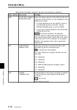
Page 121: ...bits are regenerated TC Only the timecode is regenerated UB Only the user bits ane regenerated Item number Item name Settings 603 ID CODE PRESET Select whether or not to set the ID code OFF Do not set the ID code ON Set the ID code To set the ID code 1 Set this item to ON The time data display area in the sub LCD flashes 2 Select jog mode and turn the jog dial to select the column then hold down t...

Page 122: ... line multiplex system 110 Undefined 111 Undefined Menu items in the 600s relating to the time code generator continued 606 TC OUTPUT SIGNAL IN REGEN MODE Select the signal output from the TIME CODE OUT connector during normal 1 speed playback in the following two cases For tape playback when the INT EXT switch in the timecode section is set to INT and the PRESET REGEN switch is set to REGEN For p...

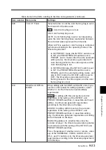
Page 123: ...ode generator regenerates according to the timecode played back from the tape Item number Item name Settings Menu items in the 600s relating to the time code generator continued 609 TCG CF FLAG Select whether or not the color framing flag is set in the blank bit of the timecode OFF Color framing flag is not set ON Color framing flag is set AUTO Color framing flag is set or not depending upon the c...

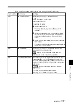
Page 124: ...ther or not to set the timecode value for the start when creating the base tape for editing see page 2 18 When this is set to ON set the start timecode value see item 603 Setting the ID code OFF Do not set ON Set 615 FIRST EDIT HEADER Set the number of seconds before the timecode value set by item 614 at which the recording starts 10 20 30 seconds Set value in this range in increments of 1 second ...

Page 125: ...For playback of an analog Betacam cassette Betacam SP etc regardless of the setting of this item the chrominance signal is blanked up to line 15 Sub Item 0 ALL LINE Specify the blanking for each line separately BLANK Regardless of the setting of other sub items blank all lines which can be specified in this menu item THROU Regardless of the setting of other sub items switch off blanking for all li...

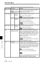
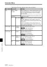
Page 126: ...matically switched on or off according to the VTR operation When recording a Non Standard signal for example if the color edge is not as good as with a proper signal the ESR can be forced on This item makes this selection AUTO ESR is switched on and off automatically ON ESR operation is forced on 706 VERTICAL BLANKING V SHIFT During noiseless variable playback when the playback signal is an odd fi...

Page 127: ...700s relating to video control continued 712 VIDEO PROCESS ON CAP LOCK 2FIELD When the CAPSTAN in the sub LCD menu or setup menu item 106 is set to 2FLD for 2 field playback select whether or not to carry out a picture shift OFF No picture shift ON Carry out picture shift Note To eliminate the adverse effect of the residual chrominance subcarrier component in the Y signal that is the result of the...

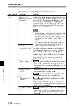
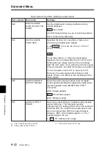
Page 128: ... a recording signal referred to below as an input signal a Betacam signal and a composite output signal referred to below as an output signal Notes Setup removal is carried out only with respect to a Batacam format CAV input signal menu setting and NTSC composite input signal It is not carried out with respect to other input signals The setup amounts specified in this menu item have no connection ...

Page 129: ...vel Default value 800H 716 CHROMA GAIN CONTROL Adjust the chroma output level Default value 800H 717 CHROMA PHASE CONTROL Adjust the chroma phase Default value 80H 718 SETUP LEVEL Adjust the setup level black level Default value 110H 719 SYSTEM PHASE SYNC Adjust the system sync phase Default value 80H 720 SYSTEM PHASE SC Adjust the system sub carrier phase Default value 0H 721 Y C DELAY For playba...

Page 130: ...pecified in this menu item THROU Regardless of the setting of other sub items switch off blanking for all lines which can be specified in this menu item In 525 mode 12 20 LINE 12 LINE 20 Specify blanking for lines 12 to 20 BLANK Carry out blanking THROU Switch off blanking In 625 mode 9 LINE 9 Specify blanking for line 9 BLANK Carry out blanking THROU Switch off blanking 10 21 LINE 10 LINE 21 Spec...

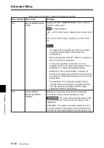
Page 131: ... VTR or when previewing while watching the VTR output signal EXT The video playback signal output phase is the same as the phase of an input video signal or external reference signal Note Whichever setting is used the correct editing results will be obtained When however you are using an external switcher to switch the video output signal from this unit for the purposes of preview select EXT This ...

Page 132: ... to a setting of 80H when the setting is less than 80H the output timing is advanced and when it is higher than 80H the output timing is delayed 80H 128 samples approx 2 7 ms 1 sample approx 20 µs 0 80 FF Setting in this range 803 DIGITAL AUDIO FADE TIME Specifies the time for cross fade or fade in out processing of digital audio signals 5 ms 10 ms 15 ms 20 ms 25 ms a 50 ms b 85 ms 115 ms c Note C...

Page 133: ... phase in the E E mode Use this setting when editing with a single VTR or when previewing while watching the VTR output signal EXT The audio playback signal output phase is the same as the phase of an input video signal or external reference video signal Note Whichever setting is used the correct editing results will be obtained When however you are using an external switcher to switch the audio o...

Page 134: ...ible to carry out video adjustment chroma adjustment or other output adjustments When item 726 is set to WIDE a number of words at the beginning and end of each line will be subject to horizontal blanking and will not be played back For playback of a composite signal in jog or variable mode according to the setting of item 705 the data will be subject to ESR edge subcarrier reducer processing 912 ...

Page 135: ...u can carry out the same operations as in the basic menu except setting of sub items For details of basic menu operation see section 6 2 2 Basic Menu Operations To set sub items 1 Confirm the JOG indicator lights If not set the unit to jog mode see page 3 3 2 After selecting the menu item holding down the STOP button turn the jog dial to select the desired sub item 3 Holding down the search button...

Page 136: ......

Page 137: ...eaning cassette may damage the heads To carry out head cleaning use the following procedure 1 Insert the cleaning cassette 2 Press the EJECT button while holding down PLAY button Head cleaning starts After a head cleaning operation which lasts for about 5 seconds the cleaning cassette is automatically ejected Note When carrying out head cleaning without using the automatic cleaning ejecting functi...

Page 138: ... dry its surface In this state the unit is not operable When the moisture has evaporated the error message disappears and the WARNING indicator goes out If ERROR 10 appears and the WARNING indicator lights immediately after powering the unit on Leave the unit powered on and wait until the indicator goes out While the indicator is lit you cannot insert a cassette When the indicator goes out and the...

Page 139: ... in fast forward rewind playback search recording or editing except for stop and still mode in units of 1 hour H04 THREADING mode Display the total number of times tape has been threaded in the unit H12 DRUM RUNNING mode resettable Same as H02 except that the count is resettable This can be used as a guide in determining when to replace the drum H13 TAPE RUNNING mode resettable Same as H03 except ...

Page 140: ... item in the LCD monitor and sub LCD To access menu item H01 quickly Press the MENU button then the CTL TC U BIT button Every time you press the CTL TC U BIT button menu item H01 or B01 is recalled alternately To exit from the hours meter Press the MENU button or SET button Digital Hours Meter sub LCD Jog and shuttle dials MENU button SET button CTL TC U BIT button LCD monitor ...

Page 141: ...me 30 minutes with BCT 30MA Rewind time Approx 3 minutes with BCT 60SX Search speed Shuttle mode Still to approx 24 times normal playback speed Betacam SX still to approx 10 times normal playback speed Betacam Betacam SP Jog mode Still to 1 times normal playback speed Variable mode Still to 1 times normal playback speed Servo lock time 0 5 seconds or less from standby on 2FD Lock Load unload time ...

Page 142: ...surable level Headroom 20 dB or 18 dB selectable Emphasis T1 50 µs T2 15 µs on off selectable in recording mode Analog output A D D A quantization 16 bits sample Frequency response 20 Hz to 20 kHz 0 5 dB 1 0 dB 0 dB at 1 kHz Dynamic range 88 dB or more at 1 kHz emphasis on 30 kHz LPF ON Distortion 0 05 or less at 1 kHz emphasis on reference level 4 dBm 30 kHz LPF ON Crosstalk 80 dB or less at 1 kH...

Page 143: ... Y 30Hz to 1 5MHz 0 5 dB 3 0dB 30Hz to 1 5MHz 0 5 dB 3 0dB S N Y 51 dB or more 48 dB or more R Y B Y 48 dB or more 45 dB or more K factor 2T pulse 2 or less 3 or less LF non linearity Y 3 or less R Y B Y 4 or less Y C delay 20 ns or less Metal tape Oxide tape Frequency response a 50 Hz to 15 kHz 1 5 dB 3 0dB 50 Hz to 15 kHz 3 0dB S N b 72 dB or more Dolby NR on weighted IEC 179A ave 50 dB or more ...

Page 144: ...MHz 0 5 dB 4 0 dB 25 Hz to 4 0 MHz 0 5 dB 6 0 dB R Y B Y 25 Hz to 2 0MHz 0 5 dB 3 0 dB 25 Hz to 1 5 MHz 0 5 dB 3 0 dB S N Y 51 dB or more 46 dB or more R Y B Y 48 dB or more 45 dB or more K factor 2T pulse 2 or less 3 or less LF non linearity Y 3 or less R Y B Y 20 ns or less 4 or less Y C delay Metal tape Oxide tape Frequency response a 50 Hz to 15 kHz 1 5 dB 3 0dB 50 Hz to 15 kHz 3 0dB S N b 62 ...

Page 145: ... 75Ω sync negative VIDEO INPUT BNC 2 in loop through connection with 75 Ω termination 1 0 Vp p 75Ω sync negative AUDIO INPUT CH 1 2 XLR 3 pin female 2 60 0 4 dBu high impedance balanced TC IN BNC 1 0 5 to 18 Vp p 10kΩ DC IN XLR 4 pin Output connectors SDI OUT 1 2 BNC 2 Serial digital 270 Mbits s SMPTE 259M ITU R BT 656 3 VIDEO OUTPUT 1 2 SUPER BNC 2 Character superimpose is possible on the 2 SUPER...

Page 146: ...C DN220SFT Carrying Case soft case for two DNW A25 A25Ps BKNW 225 docking kit for two DNW A25 A25Ps BKNW 25 DV Interface Box complied with IEEE 1394 Design and specifications are subject to change without notice Specifications Note on liquid crystal display panel The liquid crystal display fitted to this unit is manufactured with high precision technology giving a functioning pixel ratio of at lea...

Page 147: ...e information about the setup menus see chapter 6 Setup Menu To adjust the screen Use the BRIGHT and CONTRAST knobs to adjust the brightness and contrast of the screen To make the back light brighter set the BACKLGT in the sub LCD menu to HIGH see page 2 31 To display superimposed text information To display superimposed time data and text information about the operating status of the unit set the...

Page 148: ...rk 5 Recorder player selection 6 Operating mode Time data 1 Time data type Display Meaning CTL CTL counter data TCR LTC reader timecode data UBR LTC reader user bits data TCR VITC reader timecode data UBR VITC reader user bits data TCG Timecode generator timecode data UBG Timecode generator user bits data IN IN point time data OUT OUT point time data AI AUDIO IN point time data DUR The duration be...

Page 149: ...TC data field mark blank Display of fields 1 and 3 asterisk Display of fields 2 and 4 5 Recorder player selection The indication changes depending on the status of the RECORDER PLAYER indicators No display When the RECORDER and PLAYER indicators are both not lit P The PLAYER indicator is lit R The RECORDER indicator is lit 6 Operating mode The display is divided into blocks A B and C shown in the ...

Page 150: ... servo unlock REC LOCK Recording mode servo lock a Initial speed or speed stored in memory Information Displayed on the LCD Monitor SEQ REC Sequential recording mode servo unlock SEQ REC Sequential recording mode servo lock LOCK EDIT Editing mode servo unlock EDIT LOCK Editing mode servo lock JOG STILL Jog mode still picture JOG FWD Forward jog JOG REV Reverse jog SHUTTLE speed Shuttle mode VAR sp...

Page 151: ...d character then press the jog dial To delete a character from the data entry section Select Del in the character selection section To enter the date Select Date in the character selection section To enter the time Select Time in the character selection section Data entry section Character selection section Operation Cursor movement Rotate upwards Moves to the right When the last character is reac...

Page 152: ...g the BKNW 225 Note If you combine two units or separate the combined units incorrectly the units may fall down and cause body injury Follow the procedures described below for separation or combination How to attach handle DNW A25 A25P For more information refer to the operation guide for the BKNW 225 ...

Page 153: ...n PRESS move the clip downwards to release it Attaching the fixing plates If you want to be able to combine two units or separate the combined units without using tools such as screwdrivers replace the screws M3 that hold the fixing place in place with the supplied coin screws Using the Shoulder Belt Note The coin screws M4 for fixing the handle have washers When you remove the handle keep the scr...

Page 154: ...ase not supplied for two DNW A25 A25P units and accessories For one DNW A25 A25P unit use packing material Note If you pack the carrying case incorrectly the unit or accessories may fall down and cause body injury Follow the procedures described below to pack the carrying case DNW A25 A25P Battery packs Cassettes ...

Page 155: ...5 A25P units Packing the case When the AC DN2 A is attached Removable pad Pocket for accessories AC DN2 A You can stow the handle here You can stow the fixing plates for combining two DNW A25 A25P units here Note Always keep the straps fastened to prevent the units from falling out DNW A25 A25P Close the zipper Straps ...

Page 156: ...A 20 Appendixes Appendixes Placing the case on a flat surface Use the handle for lifting Using the Soft Carrying Case ...

Page 157: ...A signal that consists of a luminance signal Y and two chrominance signals Y R Y B Composite video signal A signal that consists of video sync and color burst signals CTL Control signal in the form of regular pulses recorded along a longitudinal track on the videotape By counting these pulses it is possible to determine the number of frames and hence the tape s running time Used mainly to adjust t...

Page 158: ...th of a shot by counting the timecode use drop frame mode Loading Also called threading To pull the tape out of the cassette case thread it along the specified tape path and wrap it on the drum in order to prepare it for recording or playback The VTR automatically loads the cassette tape when you insert the cassette into the cassette compartment There are two loading modes standby on mode and stan...

Page 159: ...ubcarrier continuity The SCH of a field can be checked to find out which of the four fields it represents This allows edited video signals to be joined while maintaining subcarrier continuity Search Viewing the picture or timecode by running the tape in fast forward or rewind mode in order to search for a particular scene Servo A mechanism that controls the number and phase of rotations of the hea...

Page 160: ...canning patterns of the video camera and the monitor Tape tension The tension applied to a tape For the tape to run properly while being wound on the drum it must be pulled lightly in the opposite direction to the direction of transport Improper adjustment of tape tension can cause deviations along the temporal signal axis In analog VTRs these deviations are evident as skew and distortion in the u...

Page 161: ...marks V vertical blanking The portion of the video signal that occurs between the end of one field and the beginning of the next During this time the electron beams in monitors are turned off so that they can return from the bottom of the screen to the top without showing tracks of movement on the screen When the position of v blanking is not adjusted correctly a horizontal black bar appears on th...

Page 162: ......
Page 163: ...ontents 6 1 operation 6 6 BAT END sub LCD menu 2 31 BAT NE sub LCD menu 2 31 Betacam Betacam SP 1 1 Betacam SX 1 1 Black level 625 50 mode 1 19 2 29 BREAKER button 1 24 BRIGHT CONTRAST knob 1 5 C Capstan override 4 6 Capstan servo 1 11 2 31 6 11 CAPSTAN sub LCD menu 2 31 Carrying case A 18 Cassette handling 2 6 loading ejecting 2 6 type indication 2 19 Cassette compartment 1 12 Channel condition 2...

Page 164: ...dicator 1 10 K KEY INH sub LCD menu 2 31 L LCD monitor 1 5 display A 11 power ON OFF LIGHTSW 2 32 LEVEL knob 1 19 LIGHT switch 1 6 LIGHTSW sub LCD menu 2 31 LIMITER sub LCD menu 2 23 LINE OUT sub LCD menu 2 25 M Manual editing 3 21 Menu bank operation 6 9 setup menu items 6 5 MENU button 1 13 METER switch 1 6 MIX SWAP CH 1 to 4 sub LCD menu 2 24 MONITOR sub LCD menu 2 25 MONITOR L R sub LCD menu 2...

Page 165: ...gital hours meter A 3 digital processing 6 34 editing 6 14 preroll 6 19 remote interface 6 14 tape protection 6 20 timecode generator 6 20 video control 6 24 SG sub LCD menu 2 29 Shot Data 1 2 display 5 3 5 6 Shot mark 5 1 operation menu 5 2 operations 5 4 overview 5 1 Shoulder belt A 17 Shuttle dial 1 11 mode 3 3 SHUTTLE indicator 1 10 Soft carrying case A 19 SP TAPE switch 1 9 Speaker 1 6 audio ...

Page 166: ...29 setting sub LCD menu 2 28 signal generator SG 2 29 source signal selection 2 20 test signal generator VID SG 2 30 Video control operation section 1 18 PROCESS CONTROL sub LCD menu 2 29 setup menu item 6 24 VID SG Sub LCD menu 2 30 VIDEO IN sub LCD menu 2 28 VIDEO INPUT connectors and 75 Ω termination switch 1 21 VIDEO knob 1 18 VIDEO OUTPUT connectors 1 21 2 SUPER connector A 9 VIN TRIG sub LCD...

Page 167: ...des acquéreurs de l équipement décrit dans ce manuel Sony Corporation interdit formellement la copie de quelque partie que ce soit de ce manuel ou son emploi pour tout autre but que des opérations ou entretiens de l équipement à moins d une permission écrite de Sony Corporation Das in dieser Anleitung enthaltene Material besteht aus Informationen die Eigentum der Sony Corporation sind und ausschli...

Page 168: ...Printed in Japan DNW A25 A25P SY 1998 2000 09 13 3 862 847 05 1 Sony Corporation Communication System Solutions Network Company ...

Reviews: