background image

1-4

DPP-SV55 V1 (UC, CE)

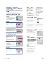
Installing the printer driver

Install the Sony DPP-SV55 Printer Driver Software for Mac OS 8.5.1/8.6/9.0 Ver. 1.0   (“printer
driver” in this manual) into your Macintosh.

1

Connect your Macintosh and the printer.

For the connections, refer to “Connecting the printer” of “Operating Instructions  – Basic
Operations.”

Note

Close all programs before running the installer.

2

Turn on the printer and start your Macintosh.

3

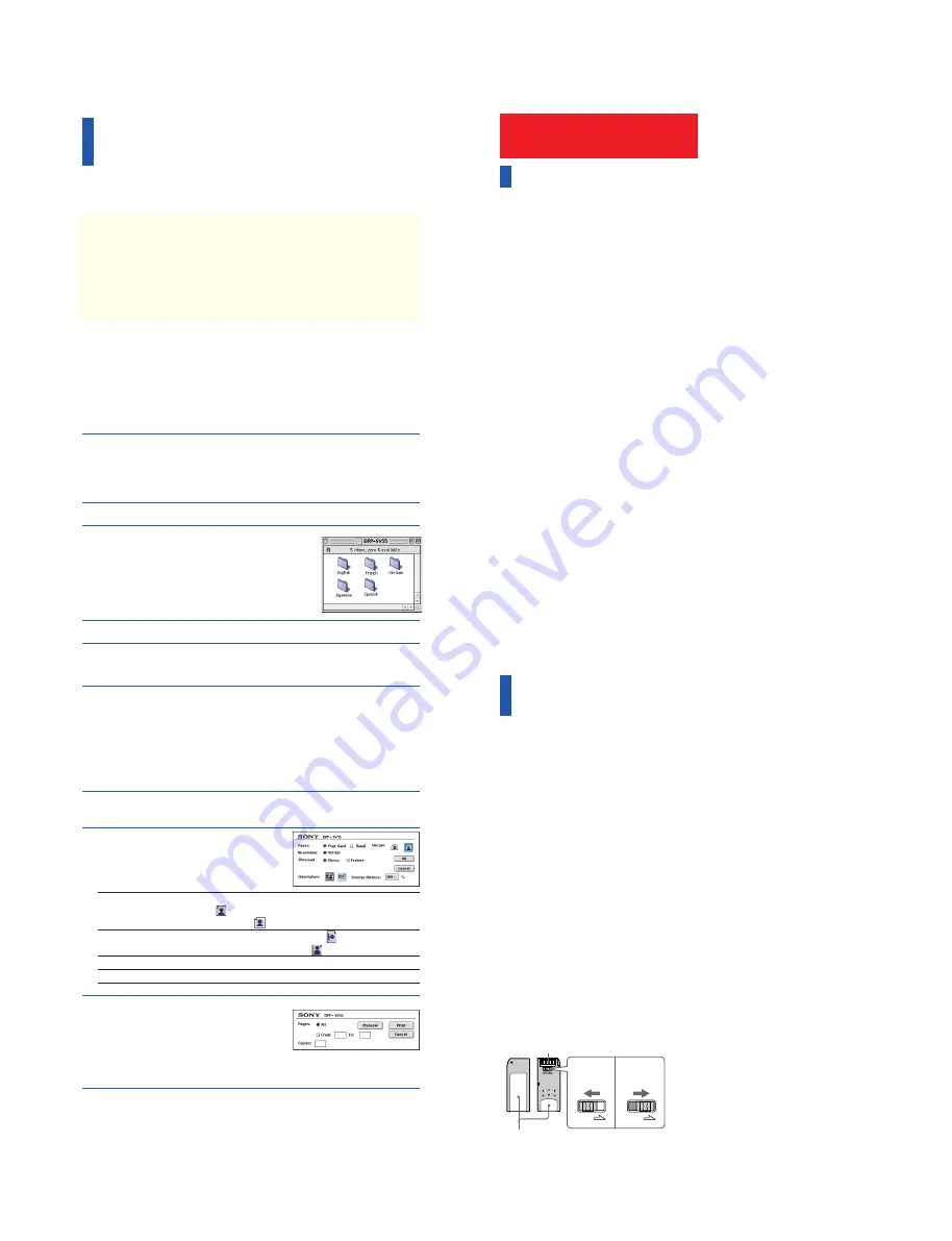
Insert the supplied CD-ROM into
your CD-ROM drive and select the
software language by double-
clicking the corresponding folder
in the CD-ROM.

The selected language folder opens.

4

Double-click “Setup Program.”

5

Click “Install.”

Installation starts.  Follow the instructions on the screen to complete installation.

Uninstalling the printer driver

When the software becomes unnecessary, remove the software as follows: In step 5, click
“Uninstall.”

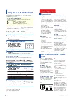
Printing from an application software

You can use an application software to print your computer’s hard disk images with the DPP-
SV55 Digital Photo Printer.

1

Select “Chooser” from the Apple menu and click “Sony DPP-
SV55” in the “Chooser.”

2

Close the “Chooser” and select
“Print Setup” from the “File”
menu and set printing in
detail.

Paper/Margin

To make Post Card Size borderless print, click “Post Card” and no
margin icon 

.  To make border Post Card Size print, click “Post

Card” and margin icon 

. To make Small Size print, click “Small.”

Orientation

To print a wide image, click landscape icon 

.

To print a tall image, click portrait icon 

 .

Overcoat

Select the overcoat type (“Glossy”/“Texture”).

Enlarge/Reduce

Select the enlarged or reduced size to be printed.

3

Click “OK” to close the dialog box
and select “Print” from the “File”
menu to start printing.

Specify the printing range and copies.  Then click
“Preview” to display the print preview or “Print”
to start printing.

Notes

• We cannot guarantee the printer operations when a

hub is used or when two or more USB devices are
connected to your computer.

•When two or more DPP-SV55 printers are

connected to your computer, you cannot operate
the printer.

• You cannot operate the printer from another USB

device being used simultaneously.

Using the printer with Macintosh

The supplied software enables you to print an image from your Macintosh with the Digital
Photo Printer DPP-SV55. To print an image from the computer, you need a commercially
available printing application software.

System requirements

To use the supplied software, you need a Macintosh computer that must meet the
following system requirements.

OS:

Mac OS 8.5.1/8.6/9.0 should be pre-installed.

Port:

USB port should be installed as standard.

RAM:

32 MB or more (64 MB or more is recommended.)

Hard disk space:

50 MB or more (It depends on the number of copies you print.)

Drive:

CD-ROM drive (for software installation)

Note

To make a print as expected, we suggest you use the
application software that allows you to check the print
preview.  Otherwise, make the image size to 1664
(dots) x 2466 (dots) and the resolution to 403 dpi.

LOCK

LOCK

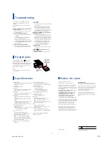
Place the label here

Connector

Write enable
position

Write
protect
position

Additional Information

Precautions

On safety

• Operate the printer on 120 V AC, 60 Hz (for

the US model) or 220 to 240 V AC, 50/60 Hz
(for the models for other areas) only.

• Be careful not to set or drop any heavy

objects on the power cord, or to damage the
power cord in any way. Never operate this
printer with a damaged power cord.

• Should any solid object or liquid fall into

the cabinet, unplug the printer and have it
checked by qualified personnel before
operating it any further.

• Never disassemble the printer.
• To disconnect the power cord, pull it out by

the plug. Never pull the power cord itself.

• When the printer is not going to be used for

an extended period of time, disconnect the
power cord from the wall outlet.

• Do not handle the printer roughly.
• To reduce the risk of electrical shock,

always unplug the printer from the
electrical outlet before cleaning and
servicing the printer.

On installation

• Avoid placing the printer in a location

subject to:
– vibration
– high humidity
– excessive dust
– direct sunlight
– extremely high or low temperatures

• Do not use electrical equipment near the

printer. The printer will not work properly
in electromagnetic fields.

• The printer is designed to operate

horizontally. Never attempt to operate the
printer in a tilted position.

• Do not place heavy objects on the printer.
• Leave enough room around the printer so

that the ventilation holes are not blocked.
Blocking these holes may cause internal
heat build-up.

On moisture condensation

If the printer is brought directly from a cold
location to warm location or placed in an
extremely warm or humid room, moisture
may condense inside the unit. In such cases
the printer will probably not work properly
and may even develop a fault if you persist in
using it. If moisture condensation occurs, turn
off the power and do not use the printer for at
least one hour.

On transport

When you transport the printer, remove the
print cartridge, paper tray, the “Memory
Stick” or PC card from the printer and put the
printer and its peripherals in the original box
with the protective packaging.
If you no longer have the original box and
packing parts, use similar packing material so
that the printer will not be damaged while
transporting.

On cleaning

Clean the cabinet, panel and controls with a
soft dry cloth, or a soft cloth lightly moistened
with a mild detergent solution. Do not use any
type of solvent, such as alcohol or benzine,
which may damage the finish.

On restrictions on duplication

If duplicating documents with the printer, pay
special attention to the following:
• Duplication of banknotes, coins, or

securities is against the law.

• Duplication of blank certificates, licenses,

passports, private securities, or unused
postal stamps is also against the law.

• TV program, films, video tapes, others’

portraits or other materials may be
copyrighted.  Unauthorized video printing
of such materials may infringe the
provisions of the copyright law.

About “Memory Stick” and PC
card

The printer can read and write “Memory
Stick” and PC card (PCMCIA ATA compatible
type II flash memory cards with a power
specification of 5V or 3.3/5V).  By using a
commercially available PC card adaptor, you
can also use Smart Media and other types of
compact flash cards.

On “Memory Stick”

There are two types of “Memory Stick”:
general “Memory Stick” and “MagicGate
Memory Stick.”  The “MagicGate Memory
Stick” is equipped with the MagicGate
copyright protection technology that uses
encryption technology.  You can use both types
of “Memory Stick” with your printer.
However, because the printer does not support
the MagicGate standards, data recorded with
the printer is not subject to MagicGate
copyright protection.

To protect “Memory Stick” images

To prevent accidental erasure of important
image data, slide the write protect switch on
the “Memory Stick” to the write protect
position when you just view the images.
Only when you write, delete data, or format a
“Memory Stick,” slide it to the write enable
position.

Notes

• You cannot use the PC cards with the power

specification of 3V only.

• Do not insert other types of PC card into the

printer’s insertion slot.  The printer may be
damaged.

• Do not drop, bent, or submit the “Memory Stick”

or PC card to external shock.

• Do not disassemble or modify the “Memory Stick”

or PC card.

• Avoid getting liquids on the “Memory Stick” or

PC card.

• Avoid using or storing the “Memory Stick” or PC

card in a location subject to:

– extremely high temperature such as the hot

inside of a car or the outdoors exposed to a
burning sun, or a place near a heater.

– direct sunlight
– high humidity
– corrosive substances
– excessive dust
– electrostatic or electronic noises
– magnetic fields

• Avoid touching the connector of the “Memory

Stick” or contacting it with a metal object.

• When attaching a label to the “Memory Stick” as

specified in the illustration, use the label supplied
for the “Memory Stick” only.  Do not use any other
labels.

• When storing and carrying the “Memory Stick” or

PC card, keep it in its original case to ensure
protection of important data.

• Avoid removing the “Memory Stick” or PC card

from the insertion slot or turning off the power of
the printer while the printer is accessing the
“Memory Stick” or PC card.  Otherwise, data may
be rendered unreadable.

• When using a compact flash card or Smart Media,

use a commercially available PC card adaptor that
is compatible with the card.   Attach the card into
the adaptor and then insert it into the printer.  For
how to install the card and adaptor, refer to the
operating instructions of the PC card adaptor.

• Avoid inserting or removing the compact flash

card or Smart Media into or out of the PC card
adaptor while the PC card adaptor is inserted in
the printer.  The data may be rendered unreadable
or erased.

Summary of Contents for DPP-SV55

Page 1: ...DIGITAL PHOTO PRINTER DPP SV55 SERVICE MANUAL Volume 1 1st Edition ...

Page 2: ...t werden Um die Gefahr eines elektrischen Schlages Feuergefahr und Verletzungen zu vermeiden sind bei Wartungsarbeiten strikt die Angaben in der Anleitung zu befolgen Andere als die angegeben Wartungsarbeiten dürfen nur von Personen ausgeführt werden die eine spezielle Befähigung dazu besitzen AVERTISSEMENT Ce manual est destiné uniquement aux personnes compétentes en charge de l entretien Afin de...

Page 3: ...ck Location 2 1 2 1 2 Board Location 2 1 2 2 Cabinet Removal Reattachment 2 1 2 3 Sensor Arrangement and Functional Description 2 2 3 Replacement of Main Parts 3 1 Replacement of Board 3 1 3 1 1 DK 41 Board 3 1 3 1 2 VS 41 Board 3 1 3 1 3 MD 41 Board 3 2 3 1 4 JD 41 Board 3 2 3 1 5 PE 41 Board 3 2 3 1 6 RM 41 Board 3 3 3 2 DC Fan 3 3 3 3 Switching Regulator 3 4 3 4 PCMCIA Ejector 3 4 3 5 Thermal H...

Page 4: ... Confirmation and Adjustment of Video Output Level 4 1 4 2 Density Adjustment During Thermal Head Replacement 4 1 5 Troubleshooting 5 1 Electrical Troubleshooting 5 1 5 2 Error Display 5 2 5 3 Mechanical Troubleshooting 5 6 5 4 Upgrade 5 7 ...

Page 5: ... Part No 3 205 183 11 Basic Operations Part No 3 205 184 11 Advanced Operations These manuals describe the information required for the actual management and operation of this unit n For details on parts number and others refer to the DPP SV55 service manual Vol 2 7 5 Packing Materials and Supplied Accessories Semiconductor Pin Assignments CD ROM Available on request This Semiconductor Pin Assignm...

Page 6: ......

Page 7: ...tions of the software supplied with the Sony Digital Photo Printer DPP SV55 First read Operating instructions Basic Operations and then read this manual and retain it for future reference For advanced operation of the printer also refer to Operating Instructions Advanced Operations DPP SV55 2000 Sony Corporation Section 1 Operating Instructions Reprinted from the operating instructions 1 1 Softwar...

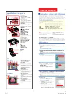
Page 8: ...inter You cannot operate the printer from another USB device being used simultaneously Printing from Your Computer Using the printer with Windows The supplied software enables you to print an image of your computer s hard disk with the Digital Photo Printer DPP SV55 You can also view copy or transfer the images stored in a Memory Stick or PC card being inserted in the printer from your computer s ...

Page 9: ...isplayed 5 Click Yes The relevant files are removed from your computer s hard disk Uninstalling the printer driver 1 Disconnect the USB cable from the printer and the computer 2 Click Start point to Settings and then click Printers 3 Right click on Sony DPP SV55 in the Printers window and select Delete from the short cut menu The confirmation dialog box is displayed 4 Click Yes The relevant files ...

Page 10: ...operate the printer in a tilted position Do not place heavy objects on the printer Leave enough room around the printer so that the ventilation holes are not blocked Blocking these holes may cause internal heat build up On moisture condensation If the printer is brought directly from a cold location to warm location or placed in an extremely warm or humid room moisture may condense inside the unit...

Page 11: ...nt paper m Check that the paper tray has paper m The thermal head may be overheated Leave the printer until the head cools down and the printer resumes printing m Remove the jammed paper if any An image in thumbnail list is not properly displayed or printed m If the image is displayed but is not be printed the file for printing is damaged m If an image is not compatible with DCF Design rule for Ca...

Page 12: ...nual thoroughly and retain it for future reference This manual explains necessary preparations and basic operations for the printer For advanced operations refer to Operating Instructions Advanced Operations For using the supplied software and for additional infromation refer to Operating Instructions Software Guide Additional Information DPP SV55 2000 Sony Corporation ...

Page 13: ...tor to VIDEO Video connecting cable supplied Memory Stick To the wall outlet To USB connector PC CARD ejection button PCcard With the notch facing left and the arrow facing forward on the left AC power cord supplied Windows Macintosh computer To USB connector Notes Also refer to the instruction manual of your computer You may not be able to use the printer and the printer driver on a network or a ...

Page 14: ...er cord 1 Video connection cable 1 Paper tray 1 CD ROM for Sony DPP SV55 Printer Driver Software for Windows 98 98SE Ver 1 0 for Mac OS 8 5 1 8 6 9 0 Ver 1 0 and Memory Stick PC card Reader Software for Windows 98 98SEVer 1 0 1 Operating Instructions Basic Operations 1 Operating Instructions Advanced Operations 1 Operating Instructions Software Guide Additional Information 1 Warranty 1 Sample Prin...

Page 15: ...tion To use the Small Size Paper stand the partition upright 2 Set the print paper into the tray Riffle the print paper Then insert the print paper with its printing surface the side with no imprint facing up and the arrow pointing in the same direction as the arrow in the tray When inserting paper insert the protective sheet together into the tray After you placed the paper remove the protective ...

Page 16: ...ill be canceled When you press PRINT while the preview image is displayed An dialog box to ask whether you want to print the image being displayed or all the selected images Select either of the two options to start printing 7 When printing ends and the print paper automatically emerges from the paper outlet remove the paper from the printer What is DPOF The DPOF is a format to record the informat...

Page 17: ...ipment does cause harmful interference to radio or television reception which can be determined by turning the equipment off and on the user is encouraged to try to correct the interference by one or more of the following measures Reorient or relocate the receiving antenna Increase the separation between the equipment and receiver Connect the equipment into an outlet on a circuit different from th...

Page 18: ...vanced operations for the printer including Editing and adjusting an image Adding a special effect to an image Making a variety of prints such as split images calendar card and sticker Changing printer settings Viewing deleting or saving images in a Memory Stick or PC card Before reading this manual read Operating Instructions Basic Operations Also refer to Operating Instructions Software Guide Ad...

Page 19: ...ictureor v to darken it Tint PressVtomakethepicture reddish or v to make it bluish Color deepness Press V to deepen the colors or v tolightenthecolors Sharpness PressVtosharpentheoutlinesor vtoresetthem Note The picture quality of the image being displayed on the screen may differ from that of the printed image Cursor Sub menu Cursor Effect menu bar Adding a special filter to an image Press B b to...

Page 20: ...d may be damaged Deleting images of a Memory Stick or PC card You can delete the selected images on a Memory Stick or PC card 1 Press INPUT SELECT to light on MEMORY STICK or PC CARD indicator 2 PressMENU The MENU bar is displayed 3 Press B b to move the cursor to DELETE FORMAT and press ENTER The cursor moves to the sub menu 4 Press V v to move the cursor to Deleting Image andpressENTER The thumb...

Page 21: ...ired image then press ENTER The window to adjust the image position is displayed 9 Press the arrow V v button to move the cursor to the desired adjustment item then press ENTER To make multiple adjustments repeat this step EachtimeyoupressENTER theimageisenlarged EachtimeyoupressENTER theimageisreduced Move MovethepicturewithB b V v thenpressENTER EachtimeyoupressENTER theimagerotates90 clockwise ...

Page 22: ... ENTER The preview of the created calendar is displayed 6 Do the following steps in Making a card to select and adjust an image and print the calendar 7 c 8 c 9 c 10 c 13 c 14 Making a split print When you select SPLIT IMAGES in the CREATIVE PRINT menu you can make a print with 4 split 9 split or 16 split images Do the following steps in Making a card to select a template select and adjust images ...

Page 23: ...1 17 DPP SV55 V1 UC CE Printed in Japan ...

Page 24: ......

Page 25: ...me assembly PCMCIA ejector Thermal head DC fan RM 41 board VS 41 board MD 41 board JD 41 board PE 41 board DK 41 board 2 2 Cabinet Removal Reattachment Upper cabinet assembly 1 Remove the two screws then remove the upper cabinet assembly in the direction indicated by the arrow 2 Attach the upper cabinet assembly in the reverse order of removal Upper cabinet assembly BV 3x20 ...

Page 26: ... the type of a ribbon Reflection type photointerrupter D901 Ribbon mark sensor Transmissive type Detects the mark of each ribbon color LED phototransistor PH905 Ribbon in sensor Reflection type x 1 Detects the existence of a ribbon cassette JD 41 board Ref Name Type Function PH964 Jamming dead sensor Reflection type x 1 Detects the paper position Reflection type photointerrupter Detects the paper ...

Page 27: ...flection type x 1 Detects the paper position Reflection type photointerrupter Detects the paper type RM 41 board Ref Name Type Function Q981 Ribbon mark sensor Transmissive type Detects the mark of each ribbon color LED phototransistor PE 41 board Side A PH971 RM 41 board Side A Q981 ...

Page 28: ......
Page 29: ...ard 1 Remove the upper cabinet assembly Refer to Section 2 2 1 2 Remove the DK 41 board Refer to Section 3 1 1 3 Remove the two screws then remove the VS 41 board 4 Remove the VS cover then disconnect the flexible flat cable 5 Attach a new VS 41 board in the reverse order of steps 1 to 4 3 1 Replacement of Board 3 1 1 DK 41 Board 1 Remove the upper cabinet assembly Refer to Section 2 2 1 2 Disconn...

Page 30: ...e MD 41 board 5 Attach a new MD 41 board in the reverse order of steps 1 to 4 3 1 4 JD 41 Board 1 Remove the upper cabinet assembly Refer to Section 2 2 1 2 Remove one screw then remove the JD 41 board 3 Disconnect one harness from the JD 41 board 4 Attach a new JD 41 board in the reverse order of steps 1 to 3 3 1 5 PE 41 Board 1 Remove the upper cabinet assembly Refer to Section 2 2 1 2 Remove th...

Page 31: ...a new DC fan in the reverse order of steps 1 to 3 3 1 6 RM 41 Board 1 Remove the upper cabinet assembly Refer to Section 2 2 1 2 Remove the DK 41 board Refer to Section 3 1 1 3 Remove the MD 41 board Refer to Section 3 1 3 4 Remove the paper feed frame assembly Refer to Section 3 6 5 Remove the four hooks then remove the paper guide assembly from the paper feed frame assembly 6 Remove the two hook...

Page 32: ... 2 1 2 Remove the DK 41 board Refer to Section 3 1 1 3 Remove the PC MS guide 4 Remove the four screws then remove the PCMCIA ejector 5 Attach a new PCMCIA injector in the reverse order of steps 1 to 4 Flexible flat cable Switching regulator Harness Mechanical deck assembly BVTP2 6x8 3 3 Switching Regulator 1 Remove the upper cabinet assembly Refer to Section 2 2 1 2 Remove the DK 41 board Refer t...

Page 33: ...to 5 3 6 Paper Feed Frame Assembly 1 Remove the upper cabinet assembly Refer to Section 2 2 1 2 Remove the DK 41 board Refer to Section 3 1 1 3 Remove the MD 41 board Refer to Section 3 1 3 4 Remove the two screws BVTT 2 6x5 then remove the paper feed frame holder from the chassis assembly 5 Remove one screw BVTP 2 6x8 then remove the paper feed frame assembly from the chassis assembly 6 Attach a ...

Page 34: ...ction 3 1 1 3 Remove the MD 41 board Refer to Section 3 1 3 4 Remove the paper feed assembly Refer to Section 3 6 5 Remove the ribbon door from the two hinges of the cassette guide in the direction indicated by the arrow 6 Attach a new chassis assembly in the reverse order of steps 1 to 5 Ribbon door Chassis assembly Cassette guide Hinges ...

Page 35: ...ng Thermal Head Replacement Before replacing the thermal head print the test pattern LINEAR STEP used as the reference of density in the old head defective head state or normal state c Be sure to make an automatic fine print in the OFF state when performing the density adjustment For the setting of the automatic fine print refer to the Operation Manual described in section 1 3 of the manual The te...

Page 36: ...ower block clockwise Decreasing the density Turn 1VR1 22 V ADJ of the power block counterclockwise Adjust 1VR1 until the obtained density becomes equal to the reference density and print the test pattern LINEAR STEP 8 When message Test1 to Test6 7 Exit is displayed with the Arrow key pressed select Exit and press the ENTER key n In steps 6 and later the test pattern is printed only using one sheet...

Page 37: ...e DK 41 board and the peripheral circuit Confirm IC101 on the DK 41 board and the peripheral circuit Trouble No PC card image can be read Remedy Confirm CN254 on the DK 41 board and the peripheral circuit Confirm IC251 on the DK 41 board and the peripheral circuit Trouble A printer is not recognized by the personal computer Remedy Confirm IC951 on the MD 41 board and the peripheral circuit Confirm...

Page 38: ...1 Move the yellow frame to Test3 using Arrow keys and and press the ENTER key 2 The monitor screen is displayed as shown below Viewing the screen Test3 Displays the status of a mechanical deck n In this mode the value cannot be changed Current STATUS Displays the current status LAST STATUS Displays the status obtained when the power was turned off previously ERR1 Displays the status obtained when ...

Page 39: ...e PES4 PES3 PES2 PES1 PES0 RM2 RM1 RM0 Contents Print error status Ribbon code Print error status PES4 PES3 PES2 PES1 PES0 Decimal State 0 0 0 0 0 0 No error 0 0 1 0 0 4 No ribbon 0 0 1 0 1 5 Ribbon completed 0 0 1 1 1 7 Ribbon code error 0 1 0 0 0 8 No paper 0 1 0 0 1 9 Paper completed 0 1 0 1 0 10 Paper length error Long 0 1 0 1 1 11 Paper length error Short 0 1 1 0 0 12 Remaining paper 1 0 0 0 ...

Page 40: ...ation was completed MDSS5 MDSS4 MDSS3 MDSS2 MDSS1 MDSS0 Decimal State 0 0 0 0 0 0 0 Idle 0 0 0 0 0 1 1 Ribbon cueing 1 0 0 0 0 1 0 2 Ribbon cueing 2 0 0 0 0 1 1 3 Ribbon cueing 3 0 0 0 1 0 0 4 Preheat 0 0 0 1 0 1 5 Cool down 0 0 1 0 0 0 8 Paper feed 0 0 1 0 0 1 9 Paper return 1 0 0 1 0 1 0 10 Paper return 2 0 0 1 0 1 1 11 Paper cueing 0 0 0 1 1 0 0 12 Paper cueing 1 0 1 0 0 0 0 16 Print 0 1 0 0 0 ...

Page 41: ... State 0 0 0 Idle 0 1 1 During Initialization 1 0 2 During normal print 1 1 3 Test mode Mode position MP2 MP1 MP0 Decimal State 0 0 0 0 M0 0 0 1 1 M1 0 1 0 2 M2 0 1 1 3 M3 1 0 0 4 M4 1 0 1 5 M5 1 1 0 6 Reserved 1 1 1 7 Reserved Print path Ribbon color COL2 COL1 COL0 Decimal State 0 0 0 0 Path 0 Paper feed 0 0 1 1 Path 1 Y 0 1 0 2 Path 2 M 0 1 1 3 Path 3 C 1 0 0 4 Path 4 O 1 0 1 5 Path 5 Paper ejec...

Page 42: ...eed roller and separation roller are dirty due to an abnormal paper feed block Replace the K paper feed frame assembly if the paper feed roller and separation roller are not dirty Replace the chassis assembly if it is abnormal the mode gear is damaged Trouble Paper is fed normally but it is ejected as blank paper Multiple sheets of paper are fed continuously Multiple paper feed Cause Incorrect pap...

Page 43: ...int can be confirmed according to the interval of a pitch Pitch interval of 18 8 mm Pinch roller abnormality Pitch interval of 20 4 mm Capstan roller abnormality Pitch interval of 37 7 mm Platen roller abnormality Cause Adhesion of dust or grease Adhesion defect in case of a pinch roller and platen roller Welding defect in case of a capstan roller Remedy Remove the mechanical deck block from the l...

Page 44: ... in the write state 4 Memory stick PC card and personal computer LEDs blink Only DPOF LEDs lights The flash memory is in the verification state 5 ALL SELECT and DPOF LEDs blink alternately Upgrading is completed n Do not pull out the power cord during upgrading 6 After completion is confirmed disconnect the power cord from the printer and take out the PC card from the printer 7 Restart the printer...

Page 45: ... 1 A commercial leakage tester such as the Simpson 229 or RCA WT 540A Follow the manufacturers instructions to use these instruments 2 A battery operated AC milliammeter The Data Precision 245 digital multimeter is suitable for this job 3 Measuring the voltage drop across a resistor by means of a VOM or battery operated AC voltmeter The limit indication is 5 25 V so analog meters must have an accu...

Page 46: ...Printed in Japan Sony Corporation 2000 12 22 Communication System Solutions Network Company 2000 DPP SV55 UC CE E 9 955 258 11 ...

Reviews: