


1-9
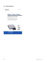
DPP-SV55 V1 (UC, CE)
The side with the Sony logo
Eject lever
Partition
Front side
Printing surface
Arrow
Paper
When inserting Small
Size print paper
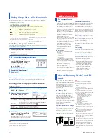
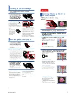
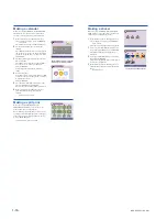
Loading the print cartridge
1
Turn on the printer and pull and open the cartridge
compartment lid.
2
Remove the protective film
and insert the print cartridge
into the printer firmly until it
clicks into place and close the
cartridge compartment lid.
To replace the print cartridge
When the print cartridge runs out, the
cartridge error indicator lights and the error
message appears on the screen.
Open the cartridge compartment lid, push up
the eject lever, remove the used print
cartridge, and then insert the new cartridge.
Notes
• If the print cartridge does
not click into place, remove
it and then re-insert it.
Only when the ink ribbon
is too slack to be loaded,
wind the ink ribbon in the
direction of the arrow to
remove the slack.
• If ink ribbon should tear, repair the ribbon with
transparent tape. There should be no problem
with using the remaining portion of the ribbon.
Before loading the print cartridge into the printer,
turn the reel until the transparent tape can no
longer be seen.
• If the print cartridge is not loaded when you turn
on the printer, the warning sound beeps and the
cartridge error indicator lights up.
• Never put your hand into the cartridge
compartment. The thermal head reaches high
temperatures, especially after repeated printing.
Notes
• If print paper does not feed automatically, the
paper error and cartridge error indicators light.
Pull out the paper tray and check the paper jam.
• When adding the print paper to a partially full
tray, make sure that the total number of sheets
does not exceed 25 for the Post Card Size or 30 for
the Small Size print paper. Do not place different
types of paper in the tray. Otherwise, paper jam or
malfunction may occur.
• Do not remove the backing from sticker print
paper before printing is completed. Otherwise,
jams or printer damage may occur.
• Do not print on the same print paper twice.
Otherwise, a malfunction or breakdown may
occur.
• If the print paper runs out when you press PRINT,
the warning sound beeps and the paper error
indicator lights.
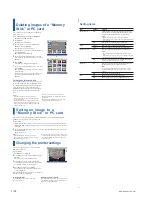
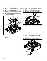
Inserting the print paper
1
Open the paper tray lid and
set the partition according to
the print paper size you use.
To use the Post Card Size Paper, lay down
the partition.
To use the Small Size Paper, stand the
partition upright.
2
Set the print paper into the tray.
Riffle the print paper. Then insert the print
paper with its printing surface (the side with
no imprint) facing up and the arrow pointing
in the same direction as the arrow in the tray.
When inserting paper, insert the protective
sheet together into the tray. After you placed
the paper, remove the protective sheet.
You can set up to 25 sheets for Post Card Size
and 30 sheets for Small Size print paper.
When inserting Small Size print paper, set in
the back of the partition.
3
Close the paper tray lid. Then
push and open the printer’s
paper tray compartment lid
and insert the paper tray into
the printer.
Insert it firmly until it clicks into place.
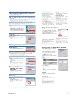
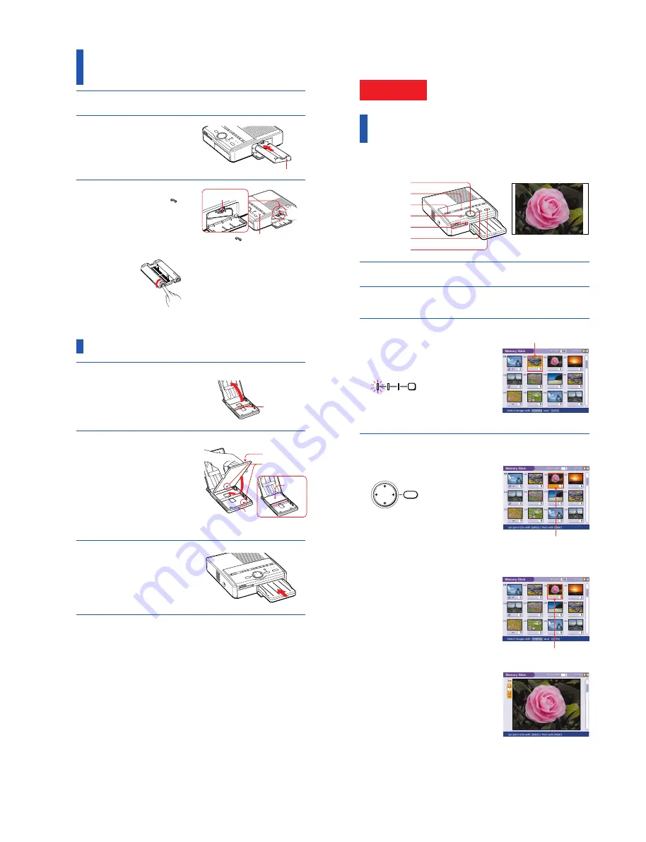
cartridge error indicator
Selected image (orange)
STICK
MEMORY
SELECT
INPUT
CARD
PC
PC
PRINT QTY
ENTER
4
3
2
PICTURE
1
5
6
Borderless standard print
Yellow frame (cursor)
The selection is canceled.
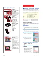
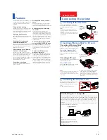
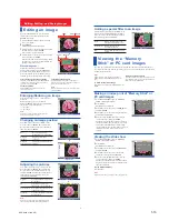
Printing
Printing “Memory Stick” or
PC card images
Printing the selected image
You can select an image recorded on the “Memory Stick” or PC card and print it in full-size
(
standard print
).
1
Insert a “Memory Stick” or PC card on which you recorded
images into the “Memory Stick” or PC card insertion slot.
2
Turn on the printer and television and set the input selector of
the television to “VIDEO.”
The POWER indicator lights in green.
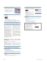
3
Press INPUT SELECT to light “MEMORY STICK” or PC CARD
indicator.
The printer accesses the “Memory Stick” or PC
card, and the recorded images are displayed as
thumbnails on the screen.
Note
Make sure that ALL and DPOF indicators of the
AUTO PRINT are off. If it is lit, press CANCEL to
turn it off.
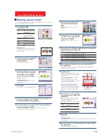
4
Press the arrow (
B/b/V/v
) button to move the yellow frame
(cursor) to the image you want to print, then press ENTER.
The image is selected and the area beneath
the image turns orange.
To display another page
When multiple pages exist, you can switch
pages. To display the next page, move the
yellow frame to the bottom line of the image list
and press
v
. To display to the previous page,
move the yellow frame to the top line and press
V
.
To cancel the selection
Move the yellow frame to the image you want
to cancel and press CANCEL. The orange area
turns gray and the selection is canceled.
To display a preview image
Move the yellow frame to the desired image,
then press PICTURE. The preview of the
selected image is displayed.
To display the preview of the next image, press
b
. To display the preview of the previous
image, press
B
.
To display the image list again, press PICTURE.
Summary of Contents for DPP-SV55
Page 1: ...DIGITAL PHOTO PRINTER DPP SV55 SERVICE MANUAL Volume 1 1st Edition ...
Page 6: ......
Page 23: ...1 17 DPP SV55 V1 UC CE Printed in Japan ...
Page 24: ......
Page 28: ......


