


3-4
DPP-SV55 V1 (UC, CE)
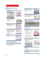
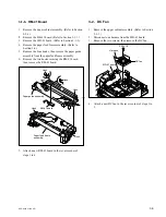
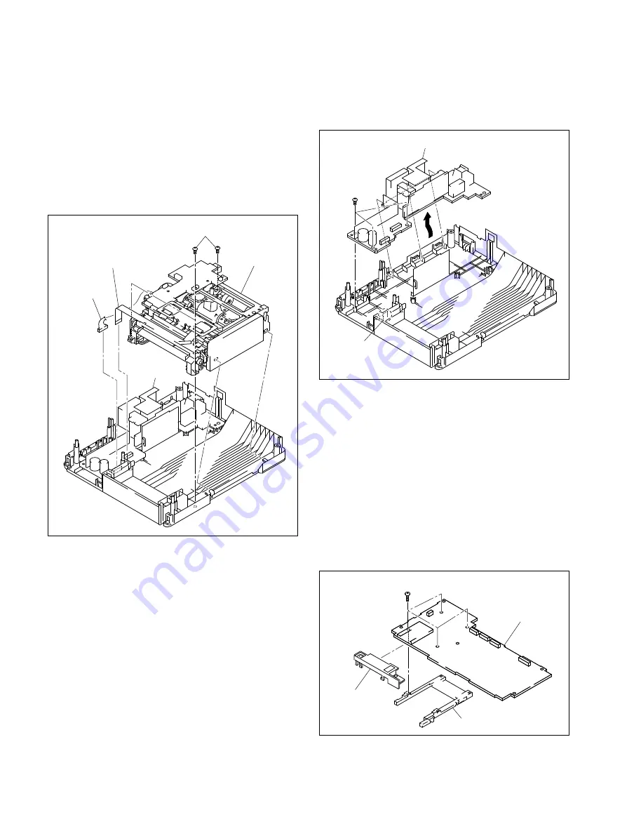
Switching regulator
Hook
BVTP2.6
x
8
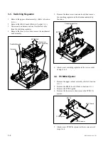
DK-41 board
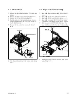
PCMCIA ejector
B2
x
10
PC/MS guide
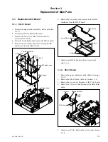
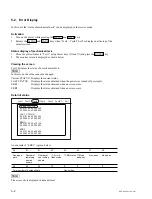
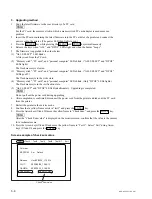
5.
Remove the three screws and one hook, then remove
the switching regulator in the direction indicated by
the arrow.
6.
Attach a new switching regulator in the reverse order
of steps 1 to 5.
3-4. PCMCIA Ejector
1.
Remove the upper cabinet assembly. (Refer to Section
2-2-1.)
2.
Remove the DK-41 board. (Refer to Section 3-1-1.)
3.
Remove the PC/MS guide.
4.
Remove the four screws, then remove the PCMCIA
ejector.
5.
Attach a new PCMCIA injector in the reverse order of
steps 1 to 4.
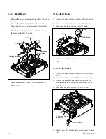
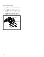
Flexible flat cable
Switching
regulator
Harness
Mechanical
deck assembly
BVTP2.6
x
8
3-3. Switching Regulator
1.
Remove the upper cabinet assembly. (Refer to Section
2-2-1.)
2.
Remove the DK-41 board. (Refer to Section 3-1-1.)
3.
Disconnect one harness and one flexible flat cable
from the switching regulator.
4.
Remove the three screws, then remove the mechanical
deck assembly.
Summary of Contents for DPP-SV55
Page 1: ...DIGITAL PHOTO PRINTER DPP SV55 SERVICE MANUAL Volume 1 1st Edition ...
Page 6: ......
Page 23: ...1 17 DPP SV55 V1 UC CE Printed in Japan ...
Page 24: ......
Page 28: ......


