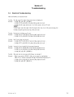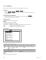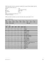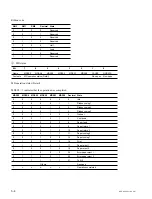
4-1
DPP-SV55 V1 (UC, CE)
Section 4
Service Mode
Activation
1.
Turn on the power while pressing the MENU and SAVE keys.
2.
Release the MENU and SAVE keys when message “Test1 to Test6/7 Exit” is displayed at the top
of the monitor screen.
4-1. Confirmation and Adjustment of Video Output Level
1.
Move the yellow frame to “Test1” using Arrow keys (
←
and
→
) and press the ENTER key.
2.
Confirm that a yellow frame exists in the color-bar character and press the ENTER key.
3.
A color-bar signal is displayed on the monitor screen.
4.
Press the Arrow keys (
↑
and
↓
) and select so that the video output level (SYNC to white 100%)
satisfies the specifications. After that, press the ENTER key.
Specifications: 1
±
0.05 Vp-p
n
To increase the video output level, press the
↑
key. To decrease it, press the
↓
key.
5.
When message “Test1 to Test6/7 Exit” is displayed with the color-bar signal disappearing, select Exit
and press the ENTER key.
4-2. Density Adjustment During Thermal Head Replacement
Before replacing the thermal head, print the test pattern (LINEAR STEP) used as the reference of density
in the old head (defective head) state or normal state.
c
.
Be sure to make an automatic fine print in the OFF state when performing the density adjustment. For
the setting of the automatic fine print, refer to the Operation Manual (described in section 1-3 of the
manual).
.
The test pattern of an old head is used only when the thermal head is not completely damaged due to
black or white stripes.
Procedure
1.
Set the ribbon and paper.
c
Use the products below as the paper to be set.
Postcard-size photo-paper SVM-25LS
2.
Select “Test6/7” in the service mode and press the ENTER key.
3.
Confirm that a yellow frame exists in the Test6 (Test Print) character on the monitor screen. After
that, select “Step” using Arrow keys (
←
and
→
) and press the ENTER key.
4.
Confirm that an orange mark exists in “Step” on the monitor screen and press the PRINT key.
A printer starts the printing of a density adjustment pattern (LINEAR STEP).
5.
Replace the thermal head.
6.
After replacement, print the test pattern (LINEAR STEP) again.
Summary of Contents for DPP-SV55
Page 1: ...DIGITAL PHOTO PRINTER DPP SV55 SERVICE MANUAL Volume 1 1st Edition ...
Page 6: ......
Page 23: ...1 17 DPP SV55 V1 UC CE Printed in Japan ...
Page 24: ......
Page 28: ......

