1-9
HDR-CX530E/CX535/CX610E/PJ530E/PJ540/PJ540E/PJ610E_L2
– ENGLISH –
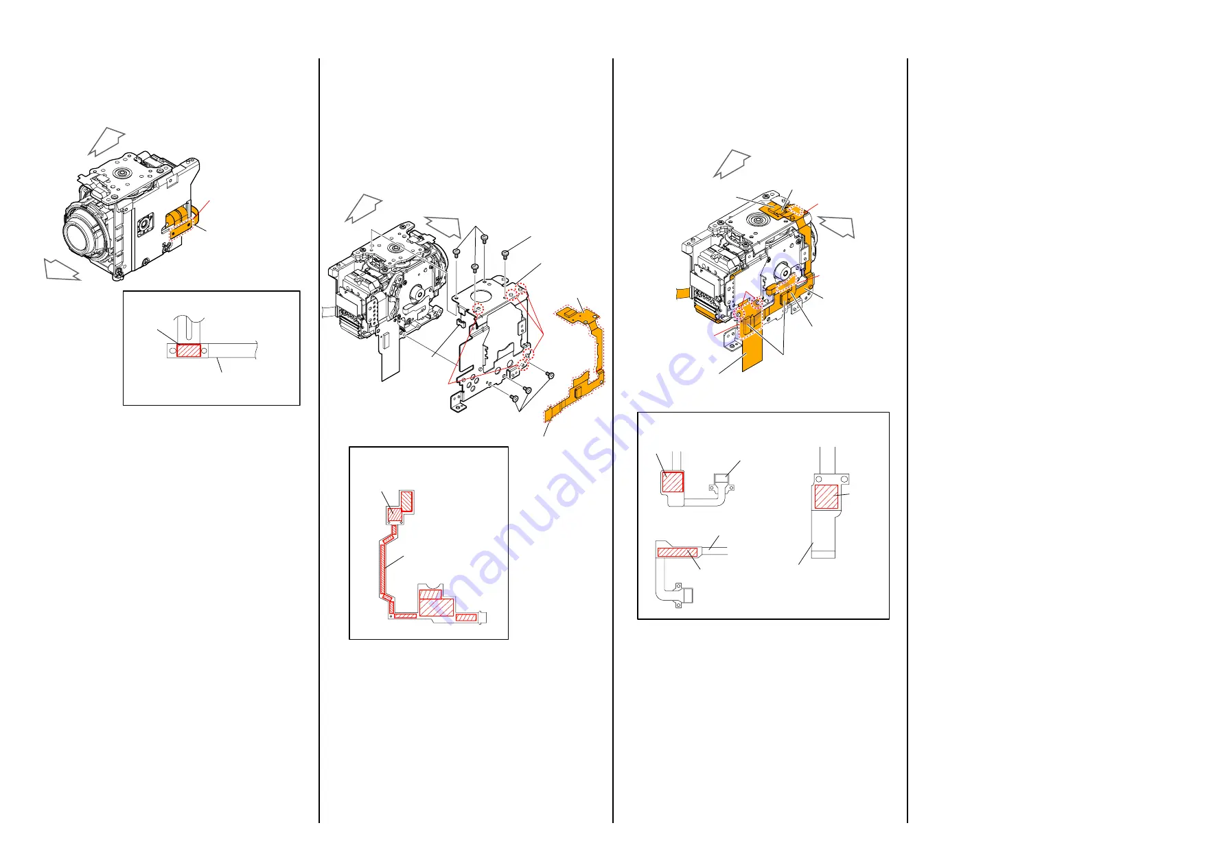
(12) Pass the FP-2189 Flexible Board through the F-SUB-B hole and
stick the Adhesive Part.
If the adhesive force is lowered, cut the Adhesive Sheet as shown
in the figure in the frame and then stick it.
Shape and sticking position
of Adhesive Sheet
Adhesive
part
FP-2189
Flexible Board
Adhesive part
FP-2189
Flexible Board
TO
P
FRONT
(13) Install the Edge of Mechanical Rubber to the Sheet Metal C and
stick the Adhesive Part while matching it with the three bosses of
the FP-2125 Flexible Board, and then tighten seven screws in the
order shown in the figure below while matching the two bosses.
Screw
(A)
Tightening torque = 0.12 ± 0.02N · m (1.2 ± 0.2kg f · cm)
Screw
(B)
Tightening torque = 0.18 ± 0.02N · m (1.8 ± 0.2kg f · cm)
If the adhesive force is lowered, cut the Adhesive Sheet as shown
in the figure in the frame and then stick it.
Screws (B)
Screws (A)
Screw (B)
Mecha
Stopper
Rubber
Bosses
Bosses
Adhesive part
Adhesive part
FP-2125
Flexible Board
FP-2125
Flexible Board
Sheet Metal C
Shape and sticking position
of Adhesive Sheet
TO
P
FRONT
1
6
5
7
4
2
3
(14) Stick the Adhesive Parts of the Motor A Flexible Board, Motor B
Flexible Board, and the FP-2126 Flexible Board while matching
the two bosses of the FP-2126 Flexible Board, and then connect
the three connectors.
If the adhesive force is lowered, cut the Adhesive Sheet as shown
in the figure in the frame and then stick it.
Shape and sticking position of Adhesive Sheet
Adhesive part
Adhesive
part
Adhesive part
Adhesive part
Adhesive part
Adhesive part
Connector
Connectors
FP-2125 Flexible
Board
FP-2126 Flexible
Board
FP-2126 Flexible
Board
Flexible Board of the Motor B
Flexible Boar
of the Motor B
Flexible Board of
the Motor A
Flexible Board of
the Motor A
Bosses
TO
P
FRONT


