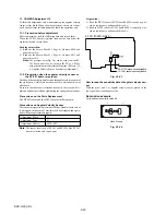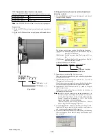
6-11
DSC-H50_ADJ
1.
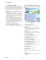
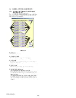
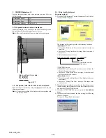
Function of Each Button on USB Serial No. Input
Screen
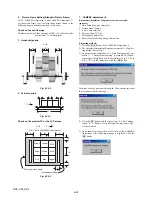
Click the
[USB SERIAL No. INPUT]
button on the Main Menu
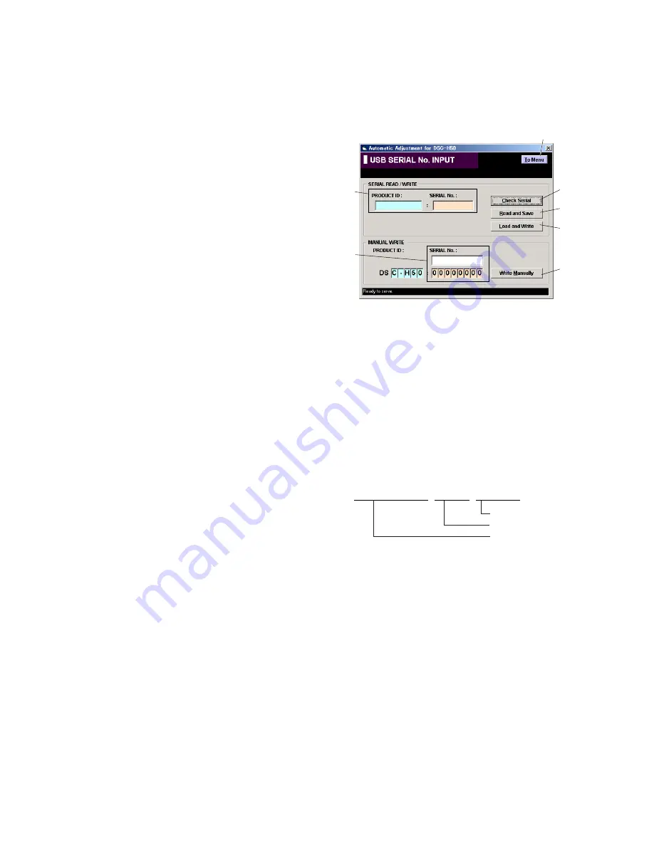
screen, and “USB SERIAL No. INPUT” screen in Fig. 6-1-13
will appear.
Fig. 6-1-13
1
[To Menu]
button
Return to the main menu.
2
Display area
The “PRODUCT ID” and “SERIAL No.” are displayed.
3
[Check Serial]
button
The USB SERIAL No. data is read from the camera and dis-
played in the display area.
4
[Read and Save]
button
The USB SERIAL No. data is read from the camera and saved
in PC as a file.
Default file name is as follows:
5
[Load and Write]
button
The USB SERIAL No. data is loaded from the file saved in
PC and written to the camera.
6
Input area
Enter “PRODUCT ID” and “SERIAL No.” when writing the
ID for service.
The “PRODUCT ID” is set from the last 5 characters of model
name if the model name is selected.
For the “SERIAL No.”, read it from the label on the camera
body and enter it.
7
[Write Manually]
button
The USB SERIAL No. data entered in the input area is written
to the camera.
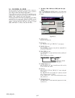
1-4.
USB SERIAL No. INPUT
The set is shipped with a unique ID (USB Serial No.) written in it.
This ID has not been written in a new board for service, and there-
fore it must be entered after the board replacement.
If original ID can be read from the board before replacement, read
it from the board before replacement using the “SERIAL READ/
WRITE” screen, and then write it after replacement.
If original ID cannot be read from the board before replacement,
write the ID for service using the “MANUAL WRITE” screen.
(The ID for service is different from the ID written when the set is
shipped.) Enter the PRODUCT ID (last 5 characters of model
name) and SERIAL No. into the screen and write them.
DSC-H50_SERIAL_xxxxxxxx_yyyymmdd.dat
Date
USB serial number
Data name
5
3
4
2
7
6
1

