2-1
DSC-S650
2. DISASSEMBLY
2-1.
DISASSEMBLY
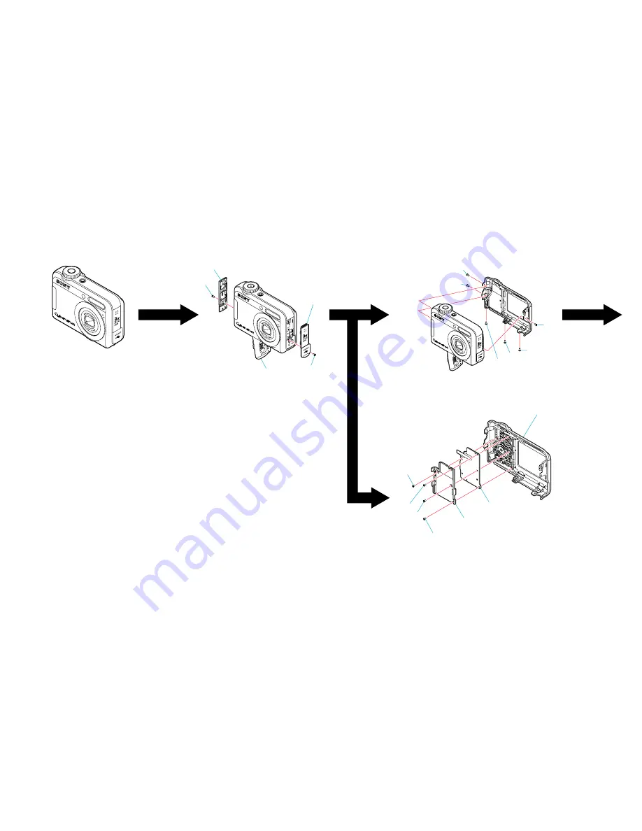
The following flow chart shows the disassembly procedure.
Front Section
(See Page 2-2)
5
4
1
1
4
3
3
2
4
3
2
1
1
1
1
3
1
2
1
Open the Battery Cover
2
Screw TP1.4
×
2.5
3
Screw TP1.7
×
3
4
Middle Cover (Right)
5
Middle Cover (Left) Assy
1
Screw TP1.4
×
3
2
Screw TP1.4
×
2.5
3
Screw TP1.7
×
4.5
4
Screw TP1.7
×
3
1
Screw TP1.4
×
2.5
2
Frame, SW
3
SW Board, Complete
4
Cabinet (Rear) Assy


