1-3 (E)
DSM-T1
1-4. Matching Connectors and Cables
1-5. Input and Output Signal of Connector
1-4. Matching Connectors and Cables
When connecting cables to various connectors on the rear panel at the time of installing or servicing,
connect the following connectors/cables or their equivalents.
DSM-T1
Matching Connector/Cable
Panel indication
Connector/cable
Sony Part No.
REF IN
BNC 75
Z
, male
1-564-742-11
IF OUT
5C-2V cable
*
1
MONITOR
SPARE
D-sub 25-pin, male
1-566-356-11 (Solderless type)
1-564-747-11 (Solder type)
*
1 : It is recommended to use the coaxial cable 5C-2V of Fujikura America Inc./Fujikura Europe Ltd. (FEL) or the equivalent.
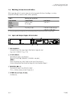
1-5. Input and Output Signal of Connector
1
REF IN (BNC
x
1)
External reference video signal input (black burst or composite sync)
Sync level = 40 IRE/0.3 V p-p, 75
Z
2
IF OUT (BNC
x
1)
Intermediate Frequency signal output
75
Z
, 0/
_
10/
_
20 dBm (selectable), 70/140 MHz (selectable)
n
The level and frequency of the output can be selected from the menu.
For more information about the menu setting, refer to the Operation Manual.
3
MONITOR (BNC
x
1)
Intermediate Frequency signal monitor output
75
Z
,
_
10 dB as reference to the IF output level
4
SPARE (D-sub 25-pin, Female)
For future use.
AC IN
BREAKER
SPARE
REF IN
IF OUT
MONITOR
1
2
1
2
3
4

