16
Location and Function of Parts
Cha
pt
er 1
Ov
er
v
ie
w
b
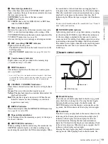
INPUT SELECT section
VIDEO IN button
Each press of this button cycles through the following
input video signal selection options.
• Composite video signal input to the VIDEO IN
connectors
• Component video signals input to the COMPONENT
VIDEO IN connectors
• S-video signal input to the S VIDEO IN connector
• SDI video signal input to the SDI IN connector (optional
DSBK-1801 board required)
• Video test signal (selected with the INT VIDEO SG
menu item
generated by the internal signal
generator
In the input selection/audio mode display section, the
VIDEO display shows the selection made with this button.
CH1,1/2 (audio channel 1 or 1/2) button
Each press of this button cycles through the following
input audio signal selection options for audio channel 1
(when in 2-channel mode) or for audio channels 1 and 2
(when in 4-channel mode).
• Analog audio signal(s) input to the AUDIO IN CH-1
connector (when in 2-channel mode) or AUDIO IN CH-
1 and CH-2 connectors (when in 4-channel mode)
• Digital audio signal in AES/EBU format input to the
DIGITAL AUDIO (AES/EBU) IN CH-1/2 connector
(optional DSBK-1801 board required)
• SDI audio signal input to the SDI IN connector (optional
DSBK-1801 board required)
• Audio test signal (selected with the INT AUDIO SG
menu item
) generated by the internal
signal generator
In the input selection/audio mode display section, the
AUDIO CH1 1/2 display shows the selection made with
this button.
CH2,3/4 (audio channel 2 or 3/4) button
Each press of this button cycles through the input audio
signal selection options for audio channel 2 (when in 2-
channel mode) or for audio channels 3 and 4 (when in 4-
channel mode). The input audio signal selection options
corresponding to those for the CH1,1/2 button described
above are available.
In the input selection/audio mode display section, the
AUDIO CH2 3/4 display shows the selection made with
this button.
SDTI/i.LINK (SDTI(QSDI) interface/i.LINK selection)
button
Selects digital video and audio signals in i.LINK-
compatible DV format, input to the
DV IN/OUT
connector. When you press this button, the i.LINK
indicator lights in the input selection/audio mode display
section.
c
MENU button
Press this button to display the menu on the monitor screen
and the time counter display. Press it again to return from
the menu display to the usual display.
On how to use the menu, see Chapter 4 “Menu Settings.”
(see page 59)
d
COUNTER SEL (selection) button
Selects the type of time data to be shown in the time
counter display. Each press of this button cycles through
three indicator display options: COUNTER (CNT: count
value of the time counter), TC (time code), and U-BIT
(user bits).
Note
When the REMOTE button in the remote control setting
section is lit, the COUNTER SEL button does not operate.
In this case, make the time data selection via the remote
equipment that is connected to the REMOTE connector on
the rear panel.
e
RESET (NO) button
Press this button to:
• reset menu settings,
• reset the time count (COUNTER) shown in the time
counter display to zero, or
• send a negative response to the prompts issued by the
unit.
f
SET (YES) button
Press this button to:
• save new settings, such as selected menu items and time
code settings, to the memory of the unit, or
• send a positive response to the prompts issued by the
unit.
g
Arrow (
JjKk
) buttons
Use these buttons to move around the menu items, and also
for setting time code and user bit data.
For details on setting time code and user bit data, see
“Using the Internal Time Code Generator” on page 49.
h
TC (time code) PRESET button
Use this button when setting an initial time code value and
user bit data.
For details on setting time code and user bit data, see “To
set the initial time code value and user bit data” on page
49.
i
SC (subcarrier) PHASE control
Turn this control to accurately adjust the subcarrier phase
of the composite video output signal of the unit with
respect to the reference video signal. Use a cross-point
(Phillips) screwdriver to turn it.
Summary of Contents for DSR-1800A
Page 26: ...26 Location and Function of Parts Chapter 1 Overview ...
Page 46: ...46 Playback Chapter 2 Recording and Playback ...
Page 82: ...82 Displaying Supplementary Status Information Chapter 4 Menu Settings ...
Page 94: ...94 Adjusting the Sync and Subcarrier Phases Chapter 5 Connections and Settings ...
Page 111: ......
Page 112: ...Sony Corporation http www sony net Printed in China ...


