56
Digitally Dubbing Signals in DVCAM Format
Ch
a
p
te
r 3
Co
nv
e
n
ien
t Fu
nc
tion
s
f
o
r E
d
itin
g
Op
er
at
io
n
Digitally Dubbing Signals
in DVCAM Format
In addition to straightforward tape dubbing, you can also
use this unit to dub automatically from the beginning of the
tape to the end through the SDTI (QSDI) or i.LINK
interface.
• To use the SDTI (QSDI) interface, the optional DSBK-
1802 board is required.
• To use the i.LINK interface, the optional DSBK-1803
board is required.
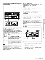
When a tape recorded on a DSR-1/1P Digital
Videocassette Recorder or DSR-130/130P Digital
Camcorder is dubbed, the ClipLink log data held in the
cassette memory is also copied.
Notes
• Use a tape recorded in the DVCAM format. A tape
recorded in DV format cannot be used as a source tape
for dubbing through the SDTI (QSDI) or i.LINK
interface.
• Regardless of the audio recording mode setting of this
unit, dubbing is performed with the original audio
recording mode unchanged (two-channel/48 kHz mode
or four-channel/32 kHz mode).
• Approximately the last 2 minutes of the tape may not be
copied because of differences in tape lengths. (If an
index picture is recorded in this portion, it may also not
be copied.)
• A continuous recorded section of approximately 5
seconds is required before the recording start point. It is
recommended to record beforehand color bars or a
similar signal at the start point of the source tape to be
dubbed on this unit.
Connections for dubbing via SDTI (QSDI)
interface
To carry out dubbing through the SDTI (QSDI) interface,
connect the REMOTE and SDTI (QSDI) IN/OUT
connectors on this unit to those on the DSR-85/85P/80/
80P/60/60P/70/70P/2000/2000P/1800/1800P/1600/
1600P.
For details of the connections and switch settings, see
“Connections for SDTI (QSDI) Dubbing” on page 92.
Connections for dubbing via i.LINK interface
To carry out dubbing through the i.LINK interface,
connect the i.DV IN/OUT connectors on this unit and the
player.
Use the following procedure.
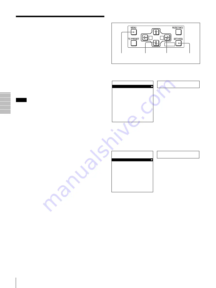
1
Press the MENU button on the menu control panel.
2
Press the
J
or
j
button to select “AUTO
FUNCTION.”
A
B
MARK
1,9
2,4
7
3,4,5
Setup menu
SYSTEM MENU
SETUP MENU
AUTO FUNCTION
HOURS METER
Monitor screen
Time counter display
Auto func
SYSTEM MENU
SETUP MENU
AUTO FUNCTION
HOURS METER
Monitor screen
Time counter display
Summary of Contents for DSR-1800P
Page 6: ...6 ...
Page 26: ...26 Location and Function of Parts Chapter 1 Overview ...
Page 46: ...46 Playback Chapter 2 Recording and Playback ...
Page 82: ...82 Displaying Supplementary Status Information Chapter 4 Menu Settings ...
Page 96: ...96 Adjusting the Sync and Subcarrier Phases Chapter 5 Connections and Settings ...
Page 119: ......
Page 120: ...Sony Corporation Printed in China http www sony net ...


