DSX-GS80/M80
16
Sony CONFIDENTIAL
For Authorized Servicer
(DSX-GS80: AEP, UK)
Memory hold connection
When the yellow power supply lead is
connected, power will always be supplied to
the memory circuit even when the ignition
switch is turned off.
Speaker connection
• Before connecting the speakers, turn the
unit off.
• Use speakers with a 2 Ω impedance or 4 Ω
to 8 Ω impedance, and with adequate
power handling capacities to avoid
damage.
Subwoofer Easy Connection
You can use a subwoofer without a power
amplifier when it is connected to a rear
speaker lead.
To enable the connection, set [SUBW MODE]
in [SUBW DIRECT] to [1] to [3].
Notes
• Preparation of the rear speaker leads is required.
• Use a subwoofer with a 2 Ω impedance or 4 Ω to 8
Ω impedance, and with adequate power handling
capacities to avoid damage.
Speaker Parallel Connection
When making the speaker parallel
connection for a high volume playback, be
sure to:
– Set [SPEAKER LOAD] in [GENERAL] to
[2 OHM].
Notes
• When using a subwoofer with dual voice coil, or
using a subwoofer by connecting the right and left
rear speaker leads, be sure to set [SPEAKER LOAD]
in [GENERAL] to [2 OHM].
• To exert the speaker’s potential, make the power
connection to the battery directly.
Front speaker
Subwoofer
FL
FR
RR
RL
Front speaker
(4 Ω to 8 Ω)
Rear speaker
(4 Ω to 8 Ω)
Subwoofer
(4 Ω to 8 Ω, dual voice
coil type)
Check your car’s auxiliary power connector,
and match the connections of leads
correctly depending on the car.
Common connection
Power connection diagram
12
continuous power
supply
Yellow
15 switched power supply Red
Auxiliary power connector
Red
Red
Yellow
Yellow
When the car without ACC position
After matching the connections and
switching power supply leads correctly,
connect the unit to the car’s power supply. If
you have any questions and problems
connecting your unit that are not covered in
this manual, consult the car dealer.
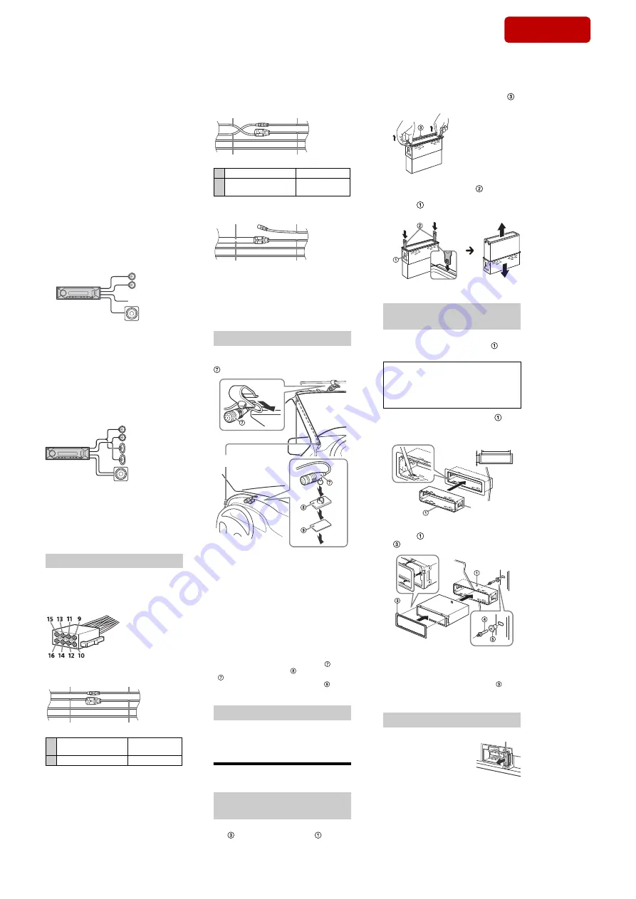
To capture your voice during handsfree
calling, you need to install the microphone
.
Cautions
• It is extremely dangerous if the cord
becomes wound around the steering
column or gearstick. Be sure to keep it and
other parts from interfering with your
driving operations.
• If airbags or any other shock-absorbing
equipment is in your car, contact the store
where you purchased this unit, or the car
dealer, before installation.
Installing the microphone
Red
Red
Yellow
Yellow
Clip (not supplied)
Notes
• When mounting on the dashboard, remove the
visor clip carefully from the microphone , then
attach the flat-mount base
to the microphone
.
• Before attaching the double-sided tape
clean
the surface of the dashboard with a dry cloth.
1
To enable the wired remote control,
set [STRG CONTROL] in [STEERING] to
[PRESET].
Installation
Before installing the unit, remove the trim
ring
and the mounting sleeve
from the
unit.
Using the wired remote control
Removing the trim ring and the
mounting sleeve
When the positions of the red and
yellow leads are inverted
12 switched power supply Yellow
15
continuous power
supply
Red
Red
Red
Yellow
Yellow
Before installing, make sure the catches on
both sides of the mounting sleeve
are
bent inwards 2 mm (
3
/
32
in).
1
Position the mounting sleeve
inside the dashboard, then bend the
claws outward for a tight fit.
2
Mount the unit onto the mounting
sleeve
, then attach the trim ring
.
Notes
• If the catches are straight or bent outwards, the
unit will not be installed securely and may spring
out.
• Make sure the 4 catches on the trim ring
are
properly engaged in the slots of the unit.
Mounting the unit in the
dashboard
CAUTION
Do not touch the left side of the unit when
removing from the dashboard. The
heatsink on the left side of the unit
remains hot right after use.
182 mm (7
1
/
4
in)
53 mm (2
1
/
8
in)
Catch
When replacing the fuse,
be sure to use one
matching the amperage
rating stated on the
original fuse. If the fuse
blows, check the power
connection and replace the
fuse. If the fuse blows again after
replacement, there may be an internal
malfunction. In such a case, consult your
nearest Sony dealer.
Fuse replacement
Fuse (15 A)
2
Insert both release keys
until they
click, and pull down the mounting
sleeve
, then pull up the unit to
separate.
Face the hook inwards.
1
Pinch both edges of the trim ring
,
then pull it out.
SYS SET
2019/10/17 21:47:35 (GMT+09:00)


