background image

DVMC-DA1

US Model

Canadian Model

SERVICE MANUAL

MEDIA CONVERTER

9-928-112-11

Power requirements

DC IN 6V jack accepts the AC-MZ60A AC power adapter
(supplied), AC 120 V, 60 Hz

Power consumption

AC 120 V, 60 Hz, 5.1 W (max., AC power adapter)

Operating temperature

10

°

C to 35

°

C (50

°

F to 95

°

F)

Operating humidity

40 % to 80 %

Storage temperature

–20

°

C to 80

°

C (–4

°

F to 176

°

F)

Storage humidity

20 % to 80 %

Dimensions (approx.)

124 

×

 44 

×

 90.5 mm (5 

×

 1

3

/

4


×

 3

5

/

8

 inches)

(w/h/d, excluding projections)

Mass (approx.)

300 g (10 oz) (unit only)

Input/output connector

S-VIDEO IN: Mini DIN 4-pin (1)
S-VIDEO OUT: Mini DIN 4-pin (1)
VIDEO IN: RCA pin (1)
VIDEO OUT: RCA pin (1)
AUDIO IN: RCA pin (2): L, R
AUDIO OUT: RCA pin (2): L, R
DV IN/OUT: S100 (100 Mbps) 4-pin (1)

Supplied accessories

Design and specifications are subject to change without
notice.

AC power adapter (AC-MZ60A)
DV connecting  cable
Audio/video connecting cable
S-video connecting cable
Operating instructions
Owner registration card
Warranty card
Important safe guard

SPECIFICATIONS

Summary of Contents for DVMC-DA1

Page 1: ...sions approx 124 44 90 5 mm 5 13 4 35 8 inches w h d excluding projections Mass approx 300 g 10 oz unit only Input output connector S VIDEO IN Mini DIN 4 pin 1 S VIDEO OUT Mini DIN 4 pin 1 VIDEO IN RCA pin 1 VIDEO OUT RCA pin 1 AUDIO IN RCA pin 2 L R AUDIO OUT RCA pin 2 L R DV IN OUT S100 100 Mbps 4 pin 1 Supplied accessories Design and specifications are subject to change without notice AC power ...

Page 2: ...ES SUPPÉMENTS PUBLIÉS PAR SONY 1 GENERAL 1 1 2 BLOCK DIAGRAMS 2 1 OVERALL BLOCK DIAGRAM 2 1 2 2 POWER BLOCK DIAGRAM 2 3 3 PRINTED WIRING BOARDS AND SCHEMATIC DIAGRAMS SWX 22 SWITCH SCHEMATIC DIAGRAM 3 2 SWX 22 SWITCH PRINTED WIRING BOARD 3 3 IFX 52 MAIN SIDE A PRINTED WIRING BOARD 3 5 IFX 52 MAIN SIDE B PRINTED WIRING BOARD 3 7 IFX 52 J CORE SCHEMATIC DIAGRAM 3 9 IFX 52 VFD SCHEMATIC DIAGRAM 3 11 ...

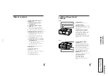
Page 3: ...of analog video signals 1 8 Copyright precautions 1 8 DV recording format 1 9 12 bit 16 bit audio modes 1 9 Locating the parts and controls 1 1 23 US Locating the parts and controls Front 1 POWER button Turns on off the media converter 2 PROTECT indicator Lights when the input picture includes a copy protection signal You cannot record the signal when this indicator is lit 3 ANALOG IN key and indi...

Page 4: ...n your TV and the other analog video unit Digital Analog 8 mm VHS Digital video 5 US Capturing images from an analog video unit using a PC page 13 14 You can capture images from an analog video unit connected to your PC via the media converter using the DV i Link connector In this case you can edit a movie or add titles using your PC You can also print out the captured images using your PC printer...

Page 5: ...perating instructions Owner registration card Warranty card Important safe guard 8 US R L AUDIO VIDEO S VIDEO DV DV IN OUT DC IN 6V Connecting an analog video unit and a DV unit via the media converter to Audio video output to S video output to DV input output Audio L white Audio R red Video yellow S video connecting cable supplied Audio video connecting cable supplied DV connecting cable supplied...

Page 6: ... to start recording 6 Start playback on the analog video unit then start recording on the DV unit The picture and sound played back on the analog video unit are recorded on the DV unit continued Note Depending on the condition of the analog video signal input to the media converter some DV units may not output the analog video signal correctly when the digital video signal is output from the media...

Page 7: ...wing digital video on your TV You can enjoy high quality digital video when you connect the DV unit to the TV via the media converter 1 Press POWER to turn on the media converter 2 Press DV IN The key indicator lights up 3 Start playback on the DV unit Pictures played back on the DV unit appear on the TV screen Playing back the audio while changing the mixing rate When playing back video recorded ...

Page 8: ...an analog video unit using a PC which is connected via the media converter 1 Press POWER to turn on the media converter 2 Press ANALOG IN The key indicator lights up 3 Start playback on the analog video unit slightly ahead of the point from which you want to start capturing images 4 Start capturing procedures on your PC The operation procedures depend on your PC and the software which you use For ...

Page 9: ...g to rest on or roll over the power cord and do not place the product where the power cord is subject to wear or abuse continued 16 US Others Unplug the product from the wall outlet and refer servicing to qualified service personnel under the following conditions When the power cord or plug is damaged or frayed If liquid has been spilled into the product If the product has been exposed to rain or ...

Page 10: ...nnector m The signal is output from the VIDEO OUT connector but not from the S VIDEO OUT connector The input signal is coming from only the S VIDEO IN connector m The signal is output both from the VIDEO OUT and S VIDEO OUT connectors The input signal is coming from both the VIDEO IN and S VIDEO IN connectors m The signal is output both from the VIDEO OUT and S VIDEO OUT connectors Notes When conn...

Page 11: ... and other rights owners Use of this copyright protection technology must be authorized by Macrovision Corporation and is intended for home and other limited viewing uses only unless otherwise authorized by Macrovision Corporation Reverse engineering of disassembly is prohibited continued 22 US 12 bit 16 bit audio modes 16 bit mode The 16 bit mode uses the whole audio area to record one stereo tra...

Page 12: ...C DC CONV 26 33 35 37 SCK 74 SO 75 115 116 117 76 75 74 14 13 1 2 16 15 SI SCK SO SI SCK SO SCK SO SI 76 81 83 82 IC602 EEPROM 2 3 4 SCK SO SI SCK SO SI SCK SO SI IC703 HI CONTROL 33 34 35 SCK STB DATA STB 50 49 31 32 106 107 FRRV TRRT TRRV AUDIO L IN AUDIO R IN AUDIO L OUT AUDIO R OUT 7 VIDEO OUT S VIDEO OUT 12 15 S Y S C C Y LINE V IC002 VIDEO SWITCH 1 3 7 IC701 VDO SWITCH RESET 6 5 7 IC704 SWIT...

Page 13: ...202 L203 Q205 Q207 FB747 L101 SW 3V L106 FL101 L305 L313 L312 L314 A 3V L102 VFD 3V L401 L403 SW 3V L503 FL505 L402 FL404 SW 3V L501 FL503 SW 3V L505 FL501 FL402 2V L502 FL504 FL401 X401 13 5MHz 18 46 45 LF301 FL301 FB301 FB302 F301 VCC1 VCC2 OUT1 7 IN1 E L701 FL701 Q302 SWITCHING D302 Q308 EVER 5V EVER 5V AU SW 5V L307 L315 L311 L316 44 OUT2 12 IN2 E Q304 SWITCHING D304 Q305 EVER 3V AOI EVER 3V A...

Page 14: ...ristic curve B unless otherwise noted Signal name XEDIT EDIT PB XREC PB REC 2 non flammable resistor 1 fusible resistor C panel designation A B Line B B Line J IN OUT direction of B LINE C adjustment for repair Circled numbers refer to waveforms Indicated by the color red THIS NOTE IS COMMON FOR WIRING BOARDS AND SCHEMATIC DIAGRAMS In addition to this the necessary note is printed in each block Tr...

Page 15: ...3 2 DVMC DA1 SWX 22 SWITCH SCHEMATIC DIAGRAM SWITCH SWX 22 Page 3 16 ...

Page 16: ...DVMC DA1 SWX 22 SWITCH PRINTED WIRING BOARD 3 3 3 4 SWITCH SWX 22 There are few cases that the part printed on this diagram isn t mounted in this model ...

Page 17: ... D304 C 1 D702 B 6 D703 C 8 D705 C 8 D706 C 8 D707 D 8 D801 A 2 IC001 E 6 IC101 C 7 IC201 D 4 IC202 C 6 IC301 B 1 IC502 A 4 IC701 A 6 IC702 B 6 IC703 B 7 Q101 D 7 Q102 D 7 Q103 E 8 Q104 E 7 Q105 E 7 Q106 E 7 Q107 D 7 Q108 D 7 Q109 D 8 Q201 F 4 Q202 F 4 Q203 F 4 Q205 E 4 Q206 E 3 Q207 E 3 Q208 E 3 Q209 C 5 Q302 C 1 Q303 C 2 Q304 C 1 Q305 D 2 Q306 D 2 Q307 B 3 Q308 B 2 Q701 A 6 Q951 A 2 ...

Page 18: ...s that the part printed on this diagram isn t mounted in this model IFX 52 BOARD CN701 C 1 CN801 F 7 CN905 B 7 D101 E 1 D102 E 1 D501 D 6 D701 A 3 IC002 E 4 IC102 D 2 IC401 C 3 IC501 C 5 IC503 E 6 IC601 B 4 IC602 B 5 IC704 A 1 Q003 E 5 Q004 E 4 Q110 D 2 Q702 B 1 Q703 B 1 Q704 B 1 Q705 B 1 ...

Page 19: ...DVMC DA1 IFX 52 J CORE SCHEMATIC DIAGRAM Refer to page 3 5 3 7 for IFX 52 BOARD printed wiring board 3 9 3 10 J CORE IFX 52 TO AUDIO TO DC CON TO MECH CON TO JACK ...

Page 20: ...DVMC DA1 3 11 3 12 IFX 52 VFD SCHEMATIC DIAGRAM Refer to page 3 5 3 7 for IFX 52 BOARD printed wiring board VFD IFX 52 TO DC CON TO AGC TO AGC TO MECH CON TO AMP ...

Page 21: ...DVMC DA1 3 13 3 14 IFX 52 MECH CON SCHEMATIC DIAGRAM Refer to page 3 5 3 7 for IFX 52 BOARD printed wiring board MECH CON IFX 52 TO AUDIO TO AGC TO AMP TO AUDIO TO AGC TO DC CON ...

Page 22: ... 16 HI IFX 52 IFX 52 HI SCHEMATIC DIAGRAM Refer to page 3 5 3 7 for IFX 52 BOARD printed wiring board TO MECH CON TO DC CON TO AGC TO MECH CON TO AUDIO TO AUDIO TO AMP TO AUDIO TO AMP TO JACK TO JACK TO JACK Page 3 2 ...

Page 23: ...DVMC DA1 3 17 3 18 IFX 52 DC CON SCHEMATIC DIAGRAM Refer to page 3 5 3 7 for IFX 52 BOARD printed wiring board DC CON IFX 52 TO AMP TO AUDIO TO AGC TO AMP TO AUDIO TO AGC AGC MECH CON DC CON F302 1 4A ...

Page 24: ...DVMC DA1 3 19 3 20 AMP IFX 52 IFX 52 AMP SCHEMATIC DIAGRAM Refer to page 3 5 3 7 for IFX 52 BOARD printed wiring board AMP TO JACK TO AGC TO JACK TO MECH CON TO DC CON DC CON TO MECH CON TO JACK ...

Page 25: ...DVMC DA1 3 21 3 22 IFX 52 AGC SCHEMATIC DIAGRAM Refer to page 3 5 3 7 for IFX 52 BOARD printed wiring board AGC IFX 52 AGC TO DC CON TO DC CON TO AMP TO MECH CON TO DC CON ...

Page 26: ...DVMC DA1 3 23 3 24 AUDIO IFX 52 IFX 52 AUDIO SCHEMATIC DIAGRAM Refer to page 3 5 3 7 for IFX 52 BOARD printed wiring board TO JACK TO DC CON TO MECH CON MECH CON TO MECH CON ANALOG IN DV IN ...

Page 27: ...ATIC DIAGRAM Refer to page 3 5 3 7 for IFX 52 BOARD printed wiring board IFX 52 CN SCHEMATIC DIAGRAM Refer to page 3 5 3 7 for IFX 52 BOARD printed wiring board JACK TO AMP TO AMP TO DC CON TO MECH CON 3 25 JACK CN IFX 52 3 26E ...

Page 28: ...er assembly and the shield upper 4 Remove the four screws 2 8 securing the IFX 52 board and remove the IFX 52 board 5 Connect the measuring instruments as shown in Fig 4 1 3 Checking the Input Signals The video signal that is supplied from the pattern generator is used as the adjustment signal of the video section Therefore the video output signal must satisfy the given specifications Connect an o...

Page 29: ...hrominance signal 0 286 Vp p 75 Ω unbalanced Audio input Pin jack Input level 327mV Input impedance 47kΩ or more 1V 0 714V 0 286V White 75 White 100 White 100 Q I 0 286V I Yellow Cyan Green Magenta Red Blue Yellow Cyan Green Magenta Red Blue Burst signal Horizontal sync signal 75 White Q Black Video output Pin jack Output signal 1Vp p 75Ω unbalanced sync negative S video output 4 pin mini DIN Lumi...

Page 30: ...to change the data copy the data built in the same set of the same destiration Note If the different set is copied the camcorder may not operate 3 To chang the data press the PAUSE button of the adjustment remote commander each time when setting new data to write the data in the non volatile memory 4 Check that the data of adjustment addresses is the initial value If not change the data to the ini...

Page 31: ...ddress 01 and set data 01 2 New data for changing are not shown in the tables because they are different depending on destination When you want to change the data copy the data built in the same set of the same destiration Note If the different set is copied the camcorder may not operate 3 To chang the data press the PAUSE button of the adjustment remote commander each time when setting new data t...

Page 32: ...ect page C address 56 set data 00 and press the PAUSE button of the adjustment remote commander digital EE mode 3 Check that the burst signal B is output to the chroma signal terminal 4 Select page 3 address 0C set data 04 and press the PAUSE button of the adjustment remote commander 5 Select page C address 2B and change the data in the range of 00 to 07 for minimum amplitude of the burst signal l...

Page 33: ...oma signal terminal of S VIDEO jack 75 Ω terminated External trigger Y signal terminal of S VIDEO jack Measuring Instrument Oscilloscope Adjustment Page C Adjustment Address 26 27 Specified Value Cr level A 714 14mVp p Cb level B 714 14mVp p Burst level C 286 16mVp p Adjusting method 1 Select page 0 address 01 and set data 01 2 Select page C address 48 set data 06 and press the PAUSE button of the...

Page 34: ...Color bar VIDEO IN terminal innput 3 579545 MHz 10Hz Measurement Point Display data of page 3 address 04 Measuring Instrument Adjustment remote commander Adjustment Page C Adjustment Address AA Specified Value 0A Adjusting method 1 Select page 0 address 01 and set data 01 2 Select page C address 56 set data 00 and press the PAUSE button of the adjustment remote commander digital EE mode 3 Select p...

Page 35: ...address The address increases when the FF button is pressed and decreases when the REW 0 button is pressed There are altogether 256 addresses from 00 to FF Changing the data Data setting The data increases when the PLAY button is pressed and decreases when the STOP p button is pressed There are altogether 256 data from 00 to FF Writing the adjustment data The PAUSE button must be pressed to write ...

Page 36: ... exploded views are not supplied 1 4 639 967 01 SCREW 0 PLATE SPECIAL HEAD 2 X 4621 825 1 CABINET LOWER ASSY 3 4 639 053 01 SHIELD LOWER 4 A 8054 856 A IFX 52 BOARD COMPLETE 5 4 982 491 01 SCREW 2 8 TAPPING 6 1 790 197 11 FFC IF SW 7 4 639 054 01 SHIELD UPPER 8 4 979 367 01 SCREW M2 6 9 A 8044 701 A CABINET UPPER BLOCK ASSY 10 4 942 636 21 EMBLEM NO 3 5 SONY 11 A 8054 858 A SWX 22 BOARD COMPLETE 1...

Page 37: ... 10 16V C106 1 119 750 11 TANTAL CHIP 22uF 20 6 3V C107 1 164 850 11 CERAMIC CHIP 18PF 5 16V C108 1 109 982 11 CERAMIC CHIP 1uF 10 10V C109 1 164 874 11 CERAMIC CHIP 100PF 5 16V C110 1 164 943 11 CERAMIC CHIP 0 01uF 10 16V C111 1 164 943 11 CERAMIC CHIP 0 01uF 10 16V C112 1 135 210 11 TANTALUM CHIP 4 7uF 20 10V C113 1 135 210 11 TANTALUM CHIP 4 7uF 20 10V C115 1 164 874 11 CERAMIC CHIP 100PF 5 16V...

Page 38: ...C CHIP 0 068uF 10 16V C362 1 164 227 11 CERAMIC CHIP 0 022uF 10 25V C401 1 164 943 11 CERAMIC CHIP 0 01uF 10 16V C402 1 164 943 11 CERAMIC CHIP 0 01uF 10 16V C403 1 125 899 11 TANTAL CHIP 220uF 20 4V C404 1 164 943 11 CERAMIC CHIP 0 01uF 10 16V C405 1 162 970 11 CERAMIC CHIP 0 01uF 10 25V C406 1 109 982 11 CERAMIC CHIP 1uF 10 10V C407 1 164 943 11 CERAMIC CHIP 0 01uF 10 16V C501 1 135 149 21 TANTA...

Page 39: ...59 535 44 IC M65511WG 600D IC501 8 759 545 03 IC HG73C037BPTL IC502 8 752 390 00 IC CXD3129R T6 IC503 8 759 566 52 IC SN104266PN TEB IC601 8 759 566 25 IC MB91191PFF G 119 BND ER IC602 8 759 445 94 IC AK6480AM E2 IC701 8 759 424 79 IC S 8423YFS T2 IC702 8 759 536 72 IC TL1596CPWR IC703 8 759 566 51 IC S579183PZ TEB IC704 8 759 524 29 IC TC74VHC257FT EL JACK J301 1 770 443 11 JACK DC POLARITY UNIFI...

Page 40: ...P 68 5 1 16W R020 1 218 981 11 RES CHIP 220K 5 1 16W R021 1 218 941 11 RES CHIP 100 5 1 16W R023 1 218 961 11 RES CHIP 4 7K 5 1 16W R024 1 218 961 11 RES CHIP 4 7K 5 1 16W R028 1 218 953 11 RES CHIP 1K 5 1 16W R029 1 218 957 11 RES CHIP 2 2K 5 1 16W R030 1 218 939 11 RES CHIP 68 5 1 16W R031 1 218 989 11 RES CHIP 1M 5 1 16W R101 1 218 973 11 RES CHIP 47K 5 1 16W R102 1 218 965 11 RES CHIP 10K 5 1 ...

Page 41: ...16W R502 1 218 961 11 RES CHIP 4 7K 5 1 16W R503 1 218 947 11 RES CHIP 330 5 1 16W R504 1 218 965 11 RES CHIP 10K 5 1 16W R505 1 218 965 11 RES CHIP 10K 5 1 16W R506 1 218 990 11 SHORT 0 R507 1 218 990 11 SHORT 0 R508 1 218 990 11 SHORT 0 R509 1 218 990 11 SHORT 0 R510 1 218 950 11 RES CHIP 560 5 1 16W R512 1 218 990 11 SHORT 0 R513 1 218 990 11 SHORT 0 R514 1 218 990 11 SHORT 0 R516 1 218 990 11 ...

Page 42: ...OR CRYSTAL 20MHz X701 1 767 450 11 VIBRATOR CERAMIC 20MHz A 8054 858 A SWX 22 BOARD COMPLETE CAPACITOR C901 1 104 847 11 TANTAL CHIP 22uF 20 4V C902 1 163 021 91 CERAMIC CHIP 0 01uF 10 50V CONNECTOR CN901 1 764 895 21 SOCKET CONNECTOR 10P DIODE D901 8 719 991 27 DIODE CL 170G CD T DV IN D902 8 719 027 84 DIODE CL 155UR G DT PROTECT D903 8 719 029 45 DIODE CL 155SD G D T ANALOG IN JUMPER RESISTOR J...

Page 43: ...DVMC DA1 58 Sony Corporation Information Technology Company 9 928 112 11 98K16026 1 Printed in Japan 1998 11 Published by Technical Response Center ...

Reviews: