106
DVP-CX777ES
•
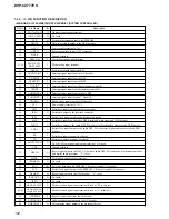
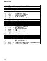
MB BOARD IC301 CXD9703R (DIGITAL SIGNAL PROCESSOR, DIGITAL SERVO PROCESSOR)
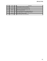
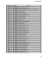
Pin No.
Pin Name
I/O
Description
1
VSS
—
Ground terminal (for digital system)
2 to 9
A0 to A7
I
Address signal input terminal
10
VDD1.8V
—
Power supply terminal (+1.8V) (for digital system)
11
XINT
O
Interrupt signal output to the system controller
12
HCS
I
Chip select signal input from the system controller
13
TESTK0
I
Input terminal for the test (normally: fixed at “L”)
14
VSS
—
Ground terminal (for digital system)
15
PDM0
O
Tracking coil drive signal output terminal
16
TESTK1
I
Input terminal for the test (normally: fixed at “L”)
17
PDM1
O
Tracking coil drive signal output terminal
18
TESTK2
I
Input terminal for the test (normally: fixed at “L”)
19
VDD3.3V
—
Power supply terminal (+3.3V) (for digital system)
20
PDM2
O
Focus coil drive signal output terminal
21
TESTK3
I
Input terminal for the test (normally: fixed at “L”)
22
PDM3
O
Focus coil drive signal output terminal
23
VSS
—
Ground terminal (for digital system)
24
XWR
I
Write enable signal input from the system controller
25
XRD
I
Read enable signal input from the system controller
26
XINT
O
Interrupt signal output to the system controller
27
XCS
I
Chip select signal input from the system controller
28
XWAIT
O
Wait signal output to the system controller
29
XMWR
O
Write enable signal output to the D-RAM
30
XCAS
O
Column address strobe signal output to the D-RAM
31
XRAS
O
Row address signal output to the D-RAM
32, 33
MDS0, MDS1
O
Spindle motor drive signal output terminal
34
VDD1.8V
—
Power supply terminal (+1.8V) (for digital system)
35
VSS
—
Ground terminal (for digital system)
36 to 43
MD0 to MD7
I/O
Two-way data bus with the D-RAM
44
VDD3.3V
—
Power supply terminal (+3.3V) (for digital system)
45
VSS
—
Ground terminal (for digital system)
46 to 53
MD8 to MD15
I/O
Two-way data bus with the D-RAM
54
VDD1.8V
—
Power supply terminal (+1.8V) (for digital system)
55
LOCK
O
EFM lock detection signal output terminal Not used
56
DOUT
O
Digital audio data output to the AV decoder and audio DSP
57
SDCK
O
Stream data bus clock signal output to the AV decoder and DSD decoder
58
XSHD
O
Stream data bus header flag signal output to the AV decoder and DSD decoder
59
XSRQ
I
Stream data bus request signal input from the AV decoder and DSD decoder
60
VSS
—
Ground terminal (for digital system)
61
XRESET
I
Reset signal input from the system controller “L”: reset
62
VDD3.3V
—
Power supply terminal (+3.3V) (for digital system)
63
XSAK
O
Stream data bus acknowledge signal output to the AV decoder and DSD decoder
64
SDEF
O
Stream data bus error flag signal output to the AV decoder and DSD decoder
65 to 74
MA0 to MA9
O
Address signal output to the D-RAM
75
VSS
—
Ground terminal (for digital system)
76
VDD1.8V
—
Power supply terminal (+1.8V) (for digital system)


